Step-by-Step Guide
introduction
CNC cutting machines are typically designed for cutting two-dimensional designs and include two axes, X and Y, used for cutting materials such as metal, wood, plastic, and others. These machines may also feature a Z axis, which adjusts the cutting nozzle's distance from the workpiece surface. However, the Z-axis control in these machines is usually not automated or performed via G-Code; instead, the operator must manually adjust the nozzle's distance. The Z-axis motors can be AC, DC, stepper, or servo motors, and depending on the type and thickness of the materials, the cutting nozzle can be equipped with air gas, plasma, waterjet, laser, etc.
Radonix Interfaces for CNC Cutting Machines
Radonix, a manufacturer of CNC controllers, has thoroughly analyzed these types of machines and designed dedicated interfaces for them. The XY-Cutter and XYZ-Cutter interfaces are specifically designed for these machines:
- XY-Cutter Interface: For machines without a Z-axis or with AC and DC motors for the Z-axis.
- XYZ-Cutter Interface: For machines with a Z-axis and stepper or servo motors.
In these interfaces, all inputs, outputs, and functions are designated with the prefix C-.
Key Features of Radonix Interfaces
- Direct execution of design files without the need for conversion to G-Code.
- The ability to select individual parts from a large file and define the sequence and direction of cutting for each piece.
- Design editing in the software with features such as Scale, Rotate, and Flip.
- Software-based correction of workpiece misalignment, especially for heavy sheets.
- Separate pauses for before, during, and after cutting.
- Reverse execution of designs and the ability to run demos without activating the cutting output.
- Execution of 2D designs on cylindrical surfaces such as pipes.
These features enable Radonix interfaces to provide more precise control and greater efficiency in the cutting process.
This interface is called XY Cutter
Radonix Interfaces for XY Cutter Machines
Radonix provides three distinct interfaces for XY Cutter machines, categorized based on the strategy and functionality of the Z Axis. This division ensures compatibility with various machine types and operational requirements. Below is a detailed explanation of these interfaces:
1. XY Cutter Interface (DC Motor-Controlled Z Axis)
The XY Cutter interface is designed for machines using DC motors to control the Z Axis. In this setup:
- The Z Axis is controlled via output links:
- C-Zfree,1 for upward movement.
- C-Zfree,-1 for downward movement.
This simple control method does not involve pulse and direction signals, making it suitable for basic XY cutting machines. Operators can activate the outputs to move the Z Axis up or down as required.
2. XYZ Cutter Interface (Manual Stepper/Servo-Controlled Z Axis)
The XYZ Cutter interface is intended for machines using stepper or servo motors in manual mode. In this configuration:
- The Z Axis is controlled via pulse and direction signals, directly connecting to the Axis control pins.
- Operators can manually adjust the Z Axis position during toolpath execution to ensure the cutting tool (e.g., plasma torch) maintains the correct height from the workpiece surface.
This interface is particularly suited for applications where manual intervention is required to maintain precision during operation.
-
nterface workspace
1- Study about different part of interface which is named and indicated in photo it means that you should get familiar with all elements like Buttons , screen , bars , volume , values , … anything on interface you have accesses
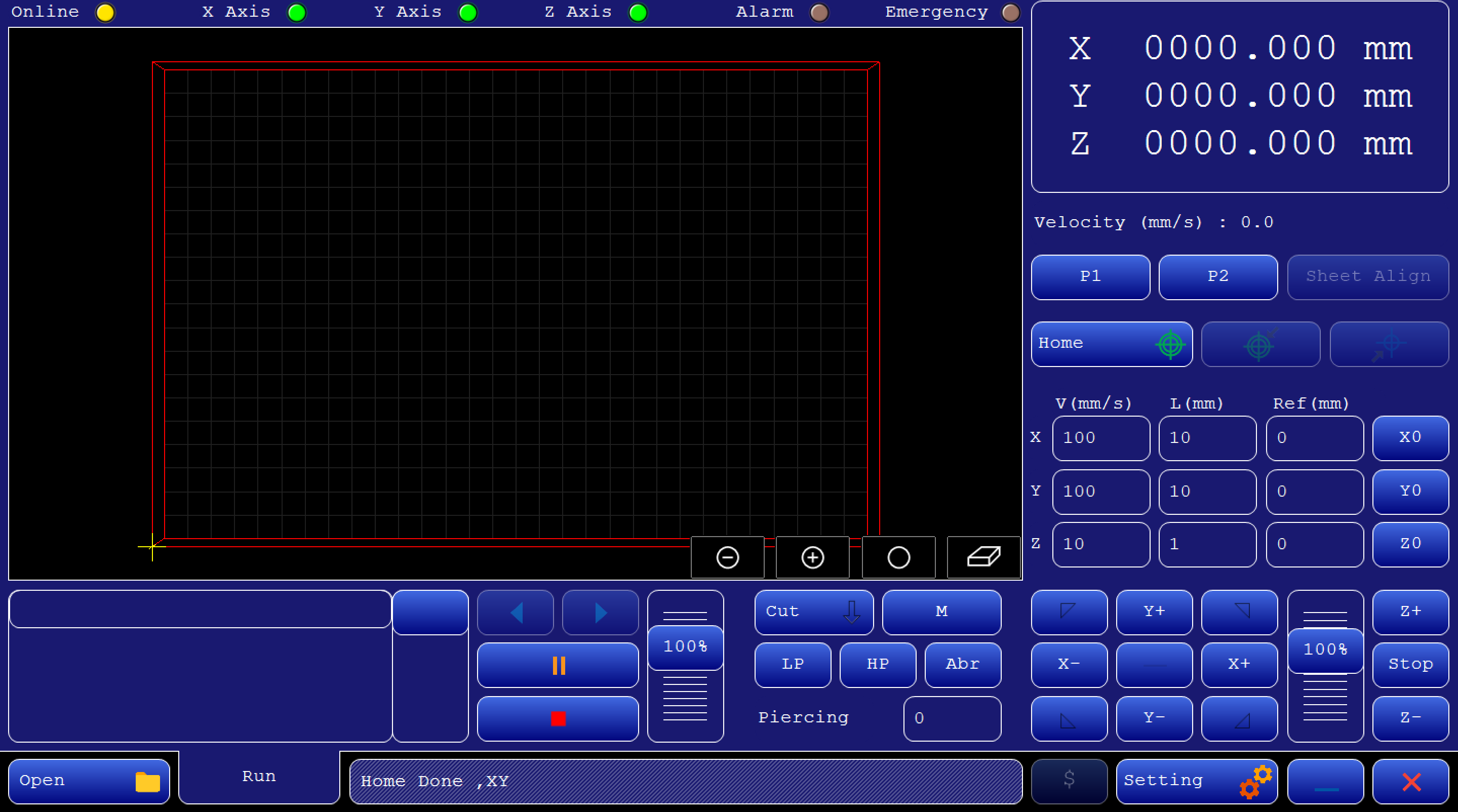
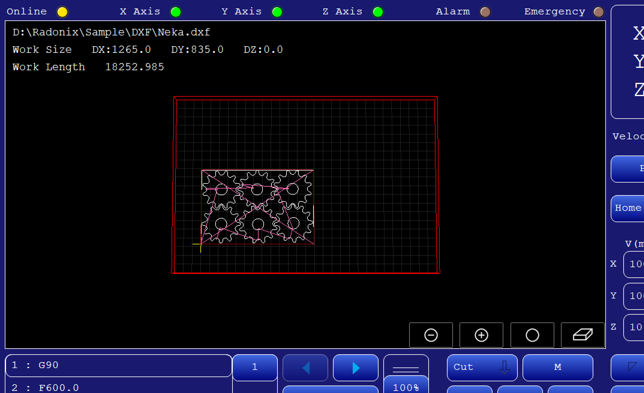
Here's a detailed description of each section and button on this CNC controller interface
Top Status Bar

- Online (Yellow Light): Indicates the machine's connection status. If the controller and software are connected, it is on.If there is no communication between the controller and the software, it will be turned off or displayed in gray color.
- X Axis, Y Axis, Z Axis (Green Lights): These lights show the operational status of each axis. Green typically means these axes are active or ready.
- Alarm, Emergency (Brown Lights): Indicators for critical safety statuses. When activated, they may change color (e.g., red) to signal an alarm, emergency stop.
Position and Speed Readouts (Right Panel)
- Position :
This position is shown based on where the reference point has been selected.
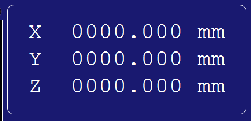
Velocity (Below Relative Position): Shows the current operational speed in mm/s, useful for monitoring real-time movement speeds.

Real-Time Reference Adjustment in Radonix Interfaces
Radonix interfaces offer a dynamic reference adjustment feature, allowing operators to redefine the reference point at any moment during the operation. This feature enhances flexibility and precision in workflows, making it suitable for diverse applications.
it means that operator can change start point of workpiece on the table.

- Manual Jogging Controls :
- Arrows (X+, X-, Y+, Y-): These buttons manually jog the machine along the X and Y axes, allowing for precise positioning adjustments by moving the tool head incrementally.
You can switch the jog mode by pressing this button according fig 01-05 and it will change to figure 01-06, changing from continuous to incremental movement. This means you can define a value in this section according fig 01-07 which has been indicated in red area , and after pressing the coordinate axis jog, the axis will move by the amount you have entered.
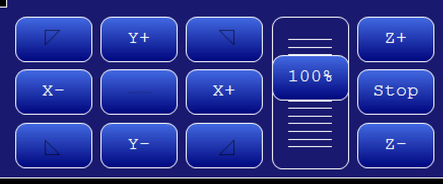


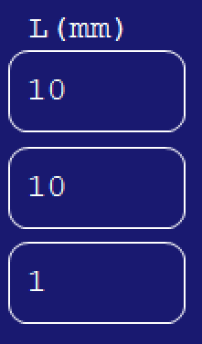
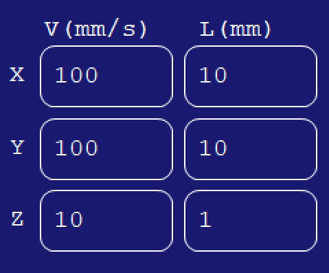
Feed Rate and Tool Parameters (Lower Right Panel)
- V (mm/s) and Step**(mm)**: Input fields for setting feed rates and movement limits along each axis. "V" controls the velocity (or speed) in mm/s, and "L" could define the step size for each manual jog.
Scroll (Vertical Slider on Bottom Right ):According to figure 01-08 which is demarcated with red area or Allows for real-time adjustment of the feed rate or speed as a percentage. This control can quickly change the speed without directly altering program values.
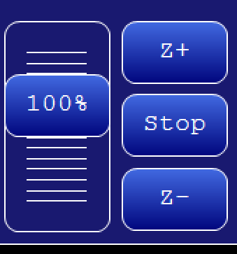
Main Program Controls
- Settings (Gear Icon): Opens the configuration menu, where detailed settings for the CNC machine can be adjusted.

- The Exit icon allows you to close the program
- The Minus icon lets you minimize it.
- The $ icon create a report from the workpiece and operator can estimate the price
Interface specification :


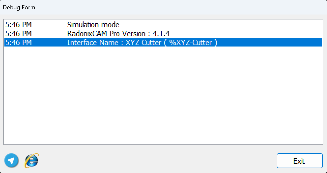
This section of the interface displays the current status and features of the system. It also updates to show alarms and processes every second. For a detailed report, double-click on this section.
Main Program Controls (Bottom Center)
- Open File (Folder Icon): Opens a file dialog for loading a CAM (Computer-Aided Manufacturing) file, typically a G-code or DXF program.

This section is dedicated to controlling G-Code execution:
-
RUN: This button starts the G-Code process.
-
Backward: The Backward button provides operators the ability to step back within the G-Code toolpath execution process. This feature is essential for troubleshooting, rechecking, or re-executing specific portions of the G-Code.
-
Pause: This button halts the toolpath.
-
Reset: This button resets the toolpath.
-
Inports
In this section, we will investigate the structure of Inports.
Essentially when Inports branch open , this kind of settings will be appeared .
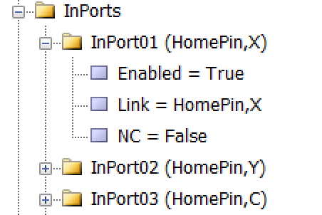
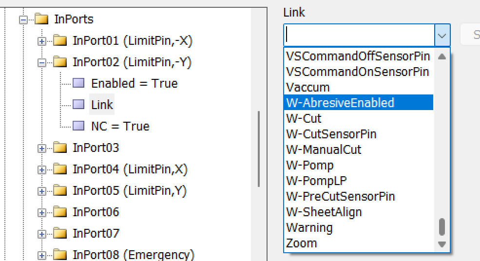
As shown in Figure No 1-09, each input has three sub-branches as detailed in the figure. The first sub-branch, 'Enable', can be set to two values: True or False. The second sub-branch, 'Link', specifies the duty or task that must be performed or checked, such as sensors, buttons, switches, etc., and includes any device that can be used as an input. The third sub-branch, 'NC', determines whether that specific input is Normally Open or Normally Closed.
Essentially, once the interface is installed, it comes with a default setup, and everyone can change the order of the input ports. For instance, we include necessary Inports which are effective and suitable for the initial launch .
The first recommended step for providing protection against any errors or mistakes is to define the Emergency link. This can be connected to a button that either stops the motors or turns off the digital outports.
Setting Up Inputs: General Overview
Configuring inputs in our CNC system is an essential step to ensure smooth operation, precise control, and safety. Inputs can be categorized into two main types based on their configuration and purpose: Hardware-Based Inputs and Software-Based Inputs. This flexibility allows the system to adapt to a wide range of applications and machine requirements.
Hardware-Based Inputs
Hardware inputs involve physical devices connected to the controller, enabling direct interaction with the machine's environment. These inputs are crucial for safety, machine control, and real-time feedback.
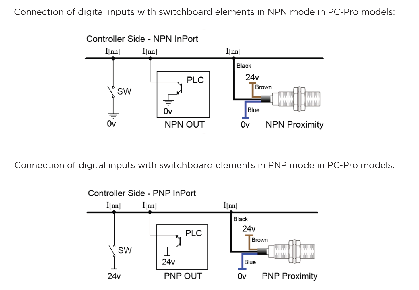
The digital inputs of Radonix controllers are named as I.[n], where n is a number greater than zero and represents the input number. These inputs are isolated by optical couplers and have low noise tolerance due to their low impedance.
The digital inputs on Radonix controllers have the capability to switch between NPN and PNP modes depending on the output of the device or sensor. The mode changeover switch must be set to PNP position for devices with PNP output and NPN position for devices with NPN output.
In various branches of industrial automation, there are equivalent terms for PNP and NPN. Some examples of these terms include: NPN = Sink = Low Active PNP = Source = High Active
In this section, we will examine the configuration of the Inputs.
Setting Up Inputs: General Overview
Configuring inputs in our CNC system is an essential step to ensure smooth operation, precise control, and safety. Inputs can be categorized into two main types based on their configuration and purpose: Hardware-Based Inputs and Software-Based Inputs. This flexibility allows the system to adapt to a wide range of applications and machine requirements.
Switching Between PNP and NPN Modes in Radonix Systems
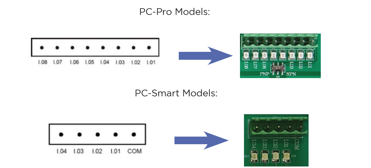
The ability to switch between PNP (positive logic) and NPN (negative logic) modes in Radonix controllers depends on the specific board model being used. This flexibility allows the system to be compatible with different wiring and sensor configurations.
- PC Pro LAN:
- A small DIP switch is present on the board.
- This switch allows users to toggle between PNP and NPN modes.
- How to Use:
- Locate the DIP switch on the board.
- Toggle the switch to the desired mode (PNP or NPN).
- Ensure the board is powered off before making changes to prevent damage.
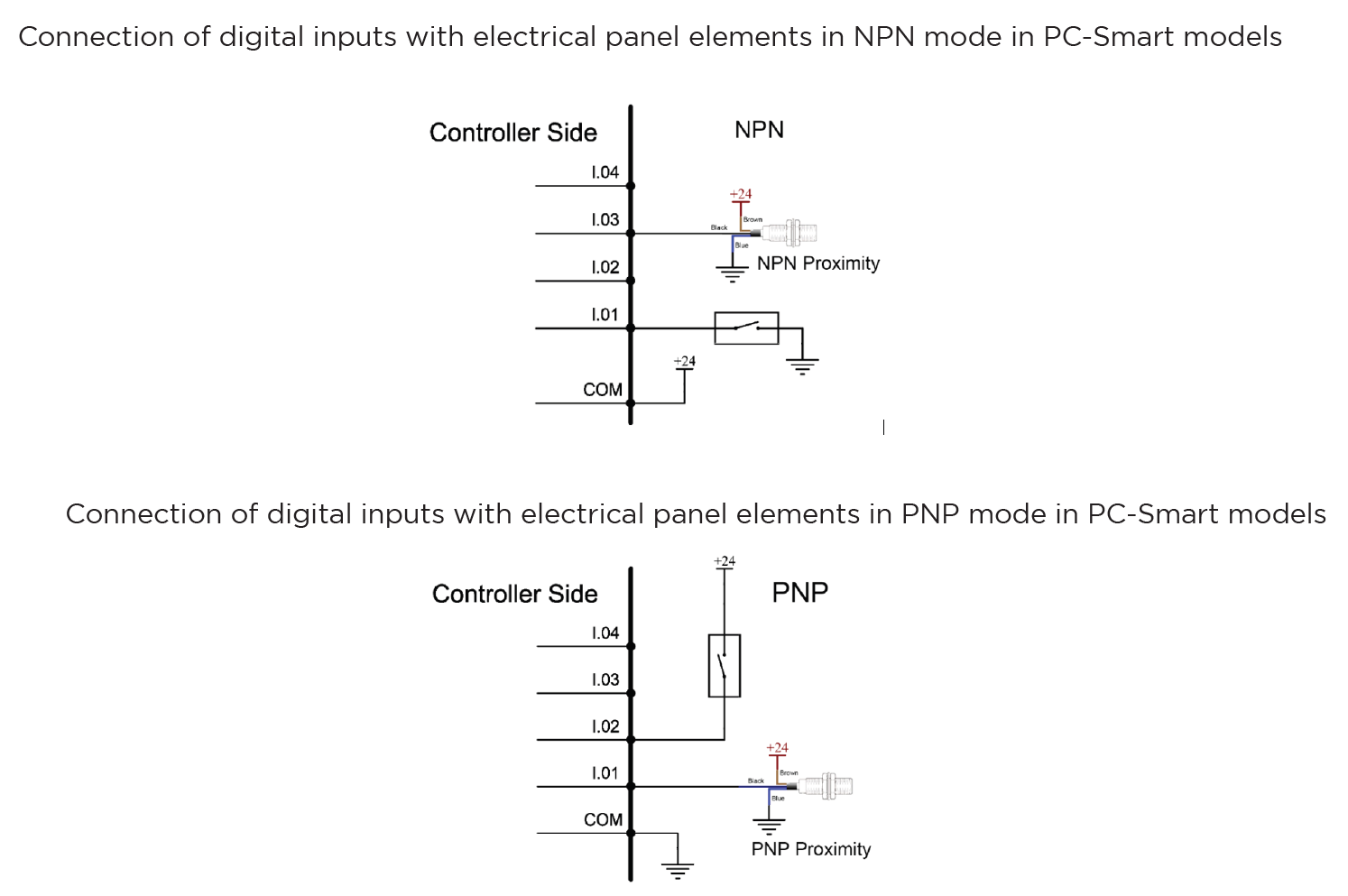
- PC Smart:
- Instead of a DIP switch, the PC Smart model uses a Come Pin for each set of 4 input pins.
- This pin allows you to define the input logic (PNP or NPN) for the corresponding inputs.
- How to Use:
-
Connect the Come Pin to the appropriate voltage (positive for PNP or ground for NPN).
1.PNP Mode (Source Mode):
- If the COM pin is connected to 0V, the input pins will be triggered (turned ON) by a 24V signal.
- In this configuration, the sensor’s output wire must provide a 24V signal to activate the input.
2.NPN Mode (Sink Mode):
- If the COM pin is connected to 24V, the input pins will be triggered (turned ON) by a 0V signal.
- In this configuration, the sensor’s output wire must pull the input to 0V to activate it.
- If the COM pin is connected to 0V, the input pins will be triggered (turned ON) by a 24V signal.
-
Each group of 4 input pins has its own Come Pin, allowing for mixed configurations within the same board.
-
Examples of Hardware Inputs:
- Limit Switches: Define physical boundaries for axis movement.
- Home Sensors: Establish the reference (Home) position for the machine most of them are Proximity
- Emergency Stop Buttons: Ensure immediate halting of operations in emergencies.
- Other Proximity Sensors: Detect objects or tools in the machine's workspace.
- Push Buttons and Selector Switches: Trigger specific machine functions or modes.
- Scanners: Measure or detect specific properties, often used in specialized processes such as Glass or gold CNC operations.
Configuration Process:
- Connection: Physically connect the hardware component (e.g., a switch or sensor) to the designated input pin on the controller.
- Input Definition: Use the controller software to define the role of the input (e.g.,
HomePin,LimitPin, or a custom input for specific functions). - Polarity Settings:
- Set the input type as Normally Open (NO) or Normally Closed (NC) based on the connected hardware's default state.
- For example:
- An NC emergency stop button remains active (closed) until pressed.
- An NO proximity sensor activates (closes) only when an object is detected.
2. Software-Based Inputs
Software-Based Inputs provide simple logical functionality to configure arbitrary links and integrate them with related physical hardware .They facilitate quick and simple installation without the need for microprogramming. Users can simply select options from a list and configure settings to maximize efficiency.

As illustrated in the figure, each input is divided into three sub-branches, as detailed below:
- Enable: This sub-branch can be set to two values: True or False.
- Link: Specifies the duty or task that needs to be performed or checked. This includes any device that can serve as an input, such as sensors, buttons, and switches.
- NC: Determines whether the specific input is Normally Open (NO) or Normally Closed (NC).
Examples of Software Inputs:
- Virtual Limit Switches:
- Use software parameters to define axis movement boundaries based on the machine's table size.
- Logical Triggers: Define conditional triggers for specific operations (e.g., When the axis reaches the limit switch ).
- Simulated Inputs: Use for testing or scenarios where physical components are unavailable.
Configuration Process:
-
Access Configuration Interface:
- Open the controller's software settings to manage inputs.
-
Define Parameters:
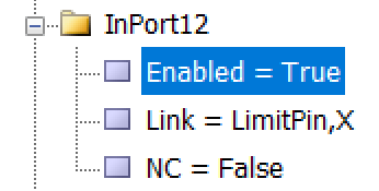
As an example to set limit Switch :
-
setting —→ System —→ In ports —→ Enabled= True
Linked = LimitPin,X
NC= True
-
Configure additional logical conditions for interlocks or simulations.
- Validate Settings:
- Test the software by CAM Pro TEST input configurations to ensure proper functionality and safety.
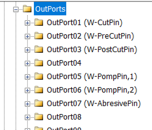
Outputs
In this section, we will examine the configuration of the Outputs.
Setting Up Inputs: General Overview
In Radonix systems, Outports are critical components that manage the output signals controlling various peripherals, such as relays, actuators, alarms, and other devices. Outputs can be categorized into two main types based on their configuration and purpose: Hardware-Based Inputs and Software-Based outputs. This flexibility allows the system to adapt to a wide range of applications and machine requirements.
1. Hardware-Based Outputs
Hardware outputs involve physical signals sent from the controller to external devices, enabling direct control of the machine’s environment. These outputs are critical for operational safety, machine actuation, and real-time command execution, ensuring efficient workflow and coordination within the CNC system.

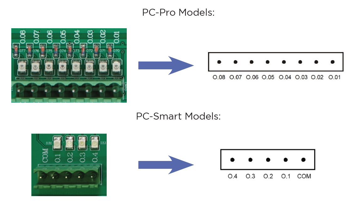
The digital outputs of Radonix controllers are named O.[n], where n is a numerical identifier greater than zero and represents the output number .
The digital outputs of Radonix controllers are named O.[n], where n is a numerical identifier greater than zero and represents the output number .
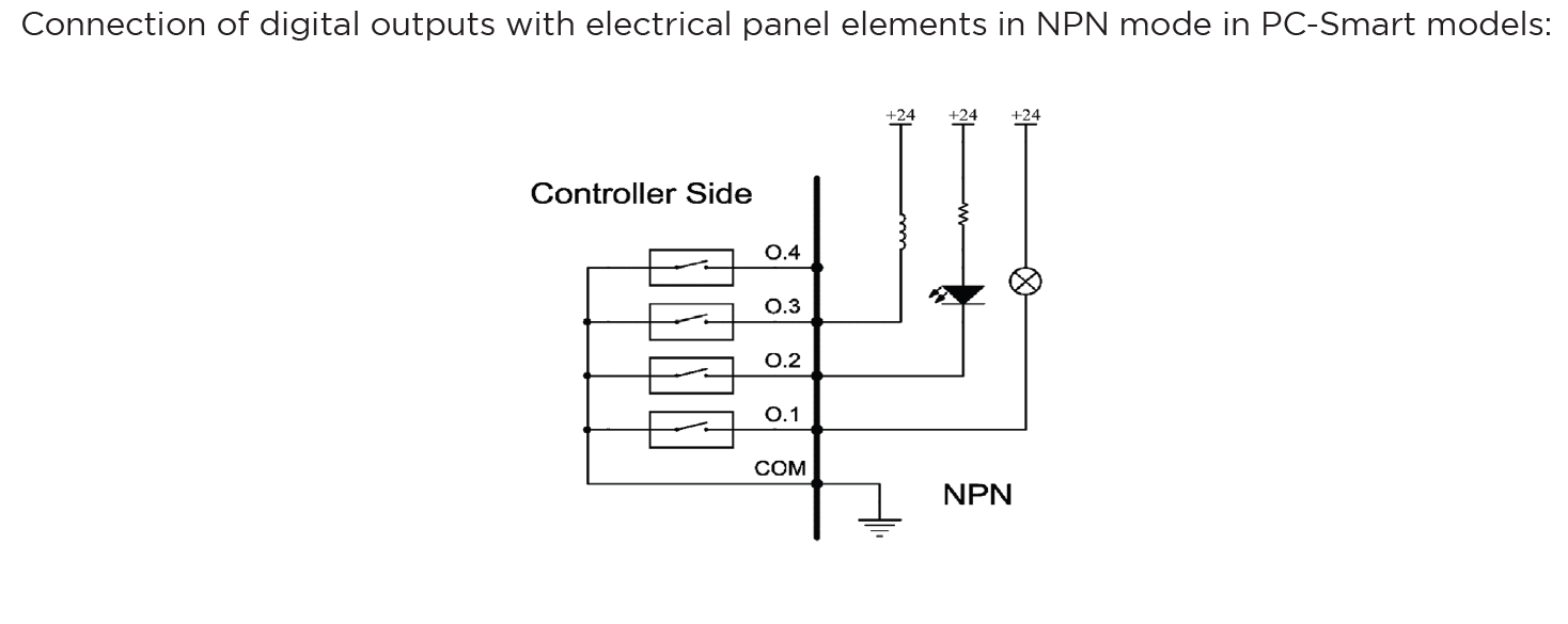
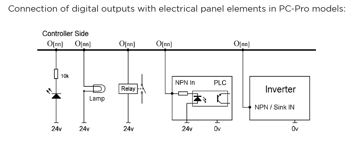
1. Output Behavior in PC-Pro LAN Models
- The PC-Pro LAN model outputs are fixed in NPN mode.
- How It Works:
- When an output is ON, it provides 0 volts by pulling the signal to ground.
- When an output is OFF, it is in a high-impedance state, effectively disconnecting the circuit.
- Wiring Consideration:
- Connected devices must be compatible with NPN logic, where the load receives voltage from a positive source and is activated when the output pulls the circuit to ground.

2. Output Behavior in PC-Smart Models
- The PC-Smart model offers a flexible configuration where outputs can operate in PNP mode or NPN mode, depending on the connection of the COM Pin.
- How It Works:
- The voltage provided by the outputs depends on what is connected to the COM Pin:
- COM Pin Connected to 24V: Outputs will provide 24 volts when activated.
- COM Pin Connected to Ground: Outputs will provide 0 volts when activated (NPN mode).
- The voltage provided by the outputs depends on what is connected to the COM Pin:
- Flexibility:
- This design allows PC-Smart models to adapt to different wiring requirements and device logic preferences.
Configuration Process for Outputs:
- Connection:
- Physically connect the hardware component (e.g., relay, electric valve , Barke , alarm) to the designated output pin on the controller.
- Ensure proper wiring based on the required logic (PNP or NPN) and voltage compatibility.
- Output Definition:
- Use the controller software to define the role of the output (e.g.,
SpindleCWpin,Coolant,SpindelCoverpinor a custom output for specific functions). - Assign the output to its intended device or operation in the system settings.
- Use the controller software to define the role of the output (e.g.,
- Logic Settings:
- Set the output logic based on the connected device's requirements:
- Active High (PNP): The output sends voltage (e.g., 24V) when activated.
- Active Low (NPN): The output pulls the signal to ground (0V) when activated.
- Set the output logic based on the connected device's requirements:
- Testing and Validation:
- After configuring, test the output to ensure it operates as intended in CAM Pro Test application.
- Use a multimeter or other diagnostic tools to verify output voltage and behavior.
2. Software-Based Outputs
Software-Based Outputs provide simple logical functionality to configure and integrate them with related physical hardware. These features are crucial for enhancing control capabilities. They facilitate quick and simple installation without the need for microprogramming. Users can simply select options from a list and configure settings to maximize efficiency.
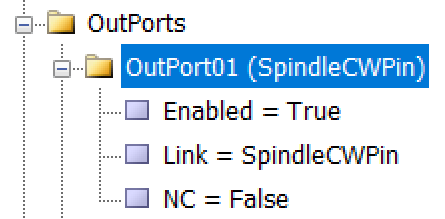
As illustrated in the figure, each output is divided into three sub-branches, as detailed below:
- Enable: This sub-branch can be set to two values: True or False.
- Link: Specifies the duty or task that needs to be performed or checked. This includes any device that can serve as an output, such as actuators, lights, and alarms.
- NC: Determines whether the specific output is Normally Open (NO) or Normally Closed (NC).
Examples of Software Outputs:
- Virtual Relays:
- Use software parameters to define activation boundaries for devices based on operational needs.
- Logical Triggers: Define conditional triggers for activating specific outputs (e.g., alarms or Relay for specific function ).
- Simulated Outputs: Employ these for testing or in scenarios where physical components are not available.
Configuration Process:
- Access the Configuration Interface:
- Navigate to the controller's software settings to manage outputs.
- Define Parameters:
-
To configure an output like an order to forward the VFD, enter parameters.
-
setting —→ System —→ Outports —→ Enabled= True
Linked = SpindleCWPin
NC= True
-
- Validate Settings:
- Test the configured software outputs to ensure they function correctly and safely, verifying their effectiveness in real-world applications.
Setting Up Inputs: Simple and Intuitive Configuration
In Radonix system, configuring inputs or Outputs is designed to be as user-friendly as possible, without requiring any microprogramming or advanced technical knowledge. All you need to do is navigate to the Inputs section of the controller interface, open the settings drawer, and select the item you need to configure. The same process applies to other sections, such as Outputs or any other functional areas.
Step-by-Step Configuration Process
- Access the Desired Section:
- Go to the section you want to configure, such as Inputs or Outputs, depending on the functionality you are setting up.
- Open the Settings Drawer:
- Within the selected section, locate the specific input branch or subsection.
- Click or expand the settings drawer to reveal the available options.
- Select the Required Item:
- Choose the input type or functionality you want to configure (e.g., limit switch, home sensor, emergency stop, or custom inputs).
- Define the specific role for the input, such as
SpindleCWPin
- Set Parameters Easily:
- Adjust the necessary parameters, such as polarity (Normally Open or Normally Closed), response delays, or logical behavior, directly from the interface.
- Save and Test:
- Save your settings and validate them through the controller interface to ensure everything is functioning as intended.
- In the end in order to finalizing you have to close program to save everything
- 1-Emergency Stop (E-Stop): A critical response mechanism in industrial settings used to halt machinery and equipment immediately in order to protect against imminent danger. This action is typically engaged through an emergency stop button or switch that, when activated, interrupts the power supply and ceases all operations, effectively minimizing the risk of accidents, injuries, or damage to the machinery and personnel.
-
Configurable Emergency Mode: An advanced feature in control systems that allows users to define and set up custom emergency responses through the system settings. This mode can be programmed to engage different levels or types of responses depending on the nature and severity of the threat detected.
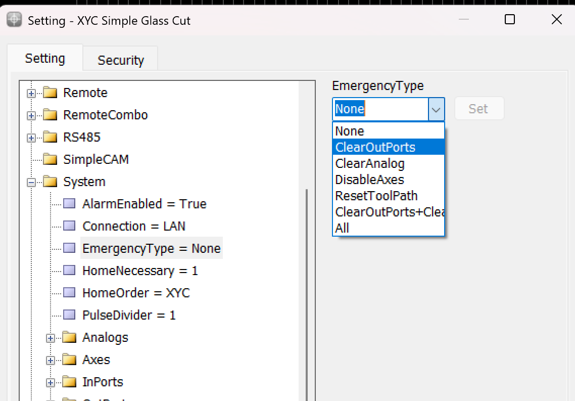
This variable is used to determine the operation that occurs when the Emergency button is pressed.
-
None: When this mode is selected, the machine operation is similar to a pause. The device stops all activities but cannot be resumed from the same point if this mode is triggered.
-
ClearOutPorts: Activating this mode stops the axes and turns off all digital output ports of the controller. This ensures that no further commands affect the machine's operation until reset.
-
ClearAnalog: This mode stops the axes and turns off all analog outputs. It's used to ensure that any variable outputs controlling aspects like tool pressure or spindle speed are deactivated.
-
DisableAxes: In this emergency mode, the axes of the machine are stopped and become inactive, which means the motors that drive the axes are disengaged, allowing them to move freely if manually pushed but not under power.
-
ResetToolPath: This mode stops the axes and resets the toolpath to the start of the program. This is useful in scenarios where the process needs to be started from the beginning, either to prevent damage or to correct an error.
-
ClearOutPorts+ClearAnalog: This comprehensive emergency mode combines the effects of ClearOutPorts and ClearAnalog, stopping all digital and analog outputs, disabling the axes, freeing the motors, and resetting the toolpath to the first coordinate. This is effectively a full reset of the system's operating state.
-
All: Selecting "All" activates all the above emergency responses, providing the maximum level of immediate system shutdown. All outputs, both digital and analog, are turned off; axes are stopped and freed; and the toolpath is reset.
-
-
**2-Home Sensors : As a usual in XY Cutter CNC machines Home sensors does not use because of the length of axis .**Home sensors are so crucial for positions it means that thanks to these sensors the position become meaningful , they are impact in defining table size the sensors are machine zero point or machine origin point when axis reach the sensors the controller detect them and it causes that a red table is created in Black Grid space so with this option each point in this area has its own position than sensors ın each axis
Indeed, home sensors are integral to the function and accuracy of CNC machines. Let's explore further how these sensors interact with the CNC controller and influence the machine workspace setup:
Role and Functionality of Home Sensors:
- Defining the Origin: Home sensors establish the machine's zero point or origin. This point serves as the reference for all other positions within the machine's operational space. It ensures that the machine knows the starting point for all axes (typically labeled X, Y, and Z).
- Impact on Table Size and Work Area Definition: The detection of the home position by these sensors directly impacts the definition of the machine’s table size. This is because the machine controller uses the origin point to calculate and define the extents of the machine’s operational area or table. The movements and operations of the machine are confined within these calculated boundaries to ensure precision and to prevent the machine from moving beyond its capable limits, which could cause damage or errors.
- Visualization on Controller Interface: When the home sensors are triggered, the CNC controller can visually depict this on its interface, often illustrated as a "red table" laid out on a "black grid" background. This visual representation helps operators to see and understand the active working area of the machine. It shows where tools can safely travel and operate, providing a clear demarcation of the workspace.
- Positional Accuracy: Each point within this defined red table area has a specific position relative to the machine’s origin point, determined by the home sensors on each axis. This arrangement allows for precise control over the machine's movements and operations, ensuring that every motion made by the machine is accurately accounted for relative to the origin, enhancing both the precision and reliability of the work performed.
- Operational Reliability: Regularly using home sensors to reestablish the machine’s origin point helps maintain operational accuracy and reliability, crucial for long-term consistent output, especially in precision-dependent applications.
Overall, home sensors not only provide a safety mechanism by defining the limits of machine operation but also enhance operational precision by establishing a clear and reliable reference point for all machining tasks. This setup ensures that every point within the operational area is accurately positioned relative to the origin, making the machine's functioning both predictable and precise.
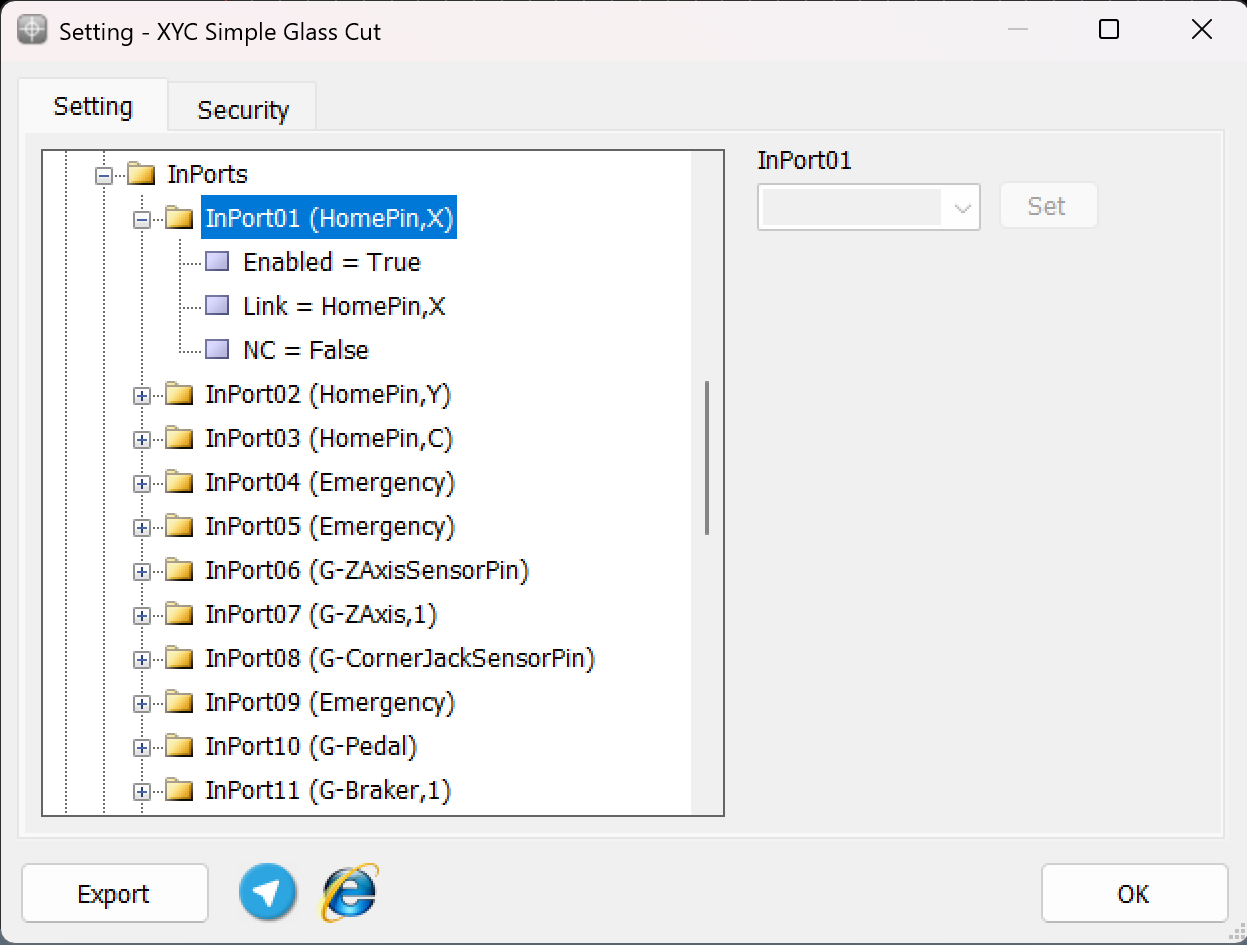
To ensure precise cessation of axis movement after issuing the Home command, the appropriate input links must be configured prior to pressing the Home button, as depicted in the above explanation. This configuration ensures that the machine accurately detects the home position for each axis.
For example:
-
The input HomePin,X is assigned to detect the X-axis home position. This means that when the X-axis sensor aligns in front of its designated home sensor, the system identifies it as the home position.
-
Similarly, other axes such as Y , C , Z require their respective input links, such as HomePin,Y or HomePin,C, to be properly set based on the machine's axes and sensor alignment.
This structured setup allows the machine to halt each axis movement accurately when it reaches its home position, ensuring safe and reliable operation during homing procedures.
-
3-Limit pin :In CNC machines, limit pins serve as an essential safety feature to prevent the machine axes from exceeding their physical boundaries. These pins are linked to hard limit switches, which are mechanical or sensor-based devices that stop the machine when triggered.
Key Points about Limit Pins:- Hard Limits:
- Hard limits rely on physical limit switches installed on the machine.
- When an axis reaches the limit switch, the corresponding input link (e.g., G-LimitPin,X, G-LimitPin,Y, or G-LimitPin,Z) is triggered.
- The machine automatically stops to avoid damage to mechanical components.
- Soft Limits:
- Soft limits are defined within the Radonix settings.
- The operator sets the allowable movement range for each axis through software, ensuring the axis does not move beyond these defined boundaries.
- These limits are monitored digitally and act as a preventive measure before reaching the physical hard limits.
- Dual Safety Mechanism:
- Combining hard limit pins with soft limits ensures maximum protection:
- Soft Limits act as the first line of defense to stop movements within software-defined boundaries.
- Hard Limits serve as a final physical safeguard to prevent any accidental overrun of the machine axes.
- Combining hard limit pins with soft limits ensures maximum protection:
Configuration of Hard Limit Pins:To set up hard limits in Radonix controllers:
- Navigate to System > InPorts in the Radonix software.
- Assign the input links for the respective limit switches:
- LimitPin,X for the X-axis hard limit.
- LimitPin,Y for the Y-axis hard limit.
- LimitPin,Z for the Z-axis hard limit.
- Ensure the Enabled parameter is set to True.
- Hard Limits:
limitPin,X
LimitPin,-X /// LimitPin,Y /// LimitPin,-Y /// LimitPin,Z /// LimitPin,-Z
-
4-Calibration : calibration refers to the process of aligning the motion value of an axis with one of the standard units or with a specific value. Common units in industrial devices are usually millimeters, centimeters, meters, inches, feet, degrees, etc., which are available for use based on the need. Therefore, the concept of calibration for the millimeter unit can be expressed as the alignment of the motion value of the desired axis with the millimeter unit. That is, in the case of measuring with measuring tools, the numerical value of the motion of the axis should be consistent with the measured value in millimeters.
At fırst step of calibration , Electronic Gear Box must be set :
An Electronic Gear Box is an integral component in modern servo systems, especially in applications that involve servo motors, like those used in automation and robotics. This technology essentially functions as a virtual gearbox that adjusts the speed and torque of a motor electronically, rather than mechanically. By manipulating the frequency and amplitude of the motor’s input signals, an electronic gearbox can change the output characteristics of the motor to suit specific tasks without needing physical gear changes.
Next step is essential for this subject is : Encoder Resolution
Encoder Resolution is a fundamental specification of servo motors, indicating the number of pulses an encoder emits for each complete revolution of the motor's shaft. This specification, expressed in pulses per revolution (PPR), is crucial for defining the precision with which the motor's position, speed, and acceleration can be controlled.
For instance, the Delta servo motor's B2 model features an encoder resolution of 160,000 pulses per revolution. This means that for every full turn of the motor shaft, the encoder generates 160,000 distinct signals. In contrast, the A2 model from the same brand boasts a much higher resolution of 1,280,000 pulses per revolution. This higher resolution allows for even finer control and more precise adjustments, which is essential in applications requiring meticulous positioning and detailed motion control.
High-resolution encoders are particularly beneficial in fields like robotics, CNC machinery, and automated assembly lines, where exact movements are paramount. The greater the encoder resolution, the smaller the movement that can be detected and controlled, enhancing the system’s accuracy and the quality of the output. This capability is crucial for optimizing the performance of high-precision tasks, ensuring that each component operates within tight tolerances and adheres to strict quality standards.
Understanding and setting the encoder resolution appropriately is a critical first step in the calibration of automated systems. It ensures that the machine operates smoothly and that each part produced meets precise specifications, thereby reducing errors and increasing overall efficiency in manufacturing processes. This detailed control over motor movements is what makes modern automated systems capable of performing complex tasks with high reliability and accuracy.
General Guide to Setting the Electronic Gear Ratio (E.G.) in Servo DrivesOverviewConfiguring the Electronic Gear Ratio (E.G.) for servo drives is crucial for optimizing their performance in applications requiring precise motion control. This guide provides a generic approach to setting E.G. in servo drives, using the Delta B2 servo drive as a specific example to illustrate the process.
Requirements- Servo drive with an integrated encoder
- Controller capable of generating pulse signals (e.g., a CNC controller)
- Technical specifications for both servo drive and controller
Step-by-Step ConfigurationStep 1: Understand Encoder Resolution
- Objective: Recognize the encoder resolution, which is the number of pulses needed for one complete rotation of the servo motor's shaft.
- General Info: Encoder resolution is specified in pulses per revolution (PPR). It determines the precision with which the servo drive can control the motor position.
Step 2: Calculate Motor Speed in Rounds Per Second
- Objective: Convert the desired motor speed from RPM (revolutions per minute) to RPS (revolutions per second) to match the controller's output frequency.
- Procedure:
- Formula: RPS=RPM/60
- This calculation adjusts the time base from minutes to seconds, facilitating synchronization with pulse output.
Step 3: Determine Required Pulses Per Second
- Objective: Calculate the total pulses per second required based on the RPS and encoder resolution.
- Procedure:
- Objective: Calculate the total pulses per second required based on the RPS and encoder resolution.
- Procedure:
-
Multiply the RPS by the encoder resolution to get the required pulses per second.
-
Example Formula: Pulses per Second=RPS × Encoder Resolution
Pulses per Second=RPS ×Encoder Resolution
-
Step 4: Set the Electronic Gear Ratio (E.G.)
- Objective: Adjust the electronic gearing to enable the controller's output to meet the servo motor's pulse requirements.
- Procedure:

E.G. Ratio Definition
The E.G. ratio is calculated by dividing the required pulse count by the controller’s pulse output capability:
E.G. = Required pulses per second / Controller’s pulse capability
To ensure proper operation, configure the controller so that its pulse capability meets or exceeds the calculated E.G. ratio.
Example: Delta B2 Servo Drive
Motor speed: 3,000 revolutions per minute (RPM)
Encoder resolution: 160,000 pulses per revolution (PPR)
Controller’s pulse capability: 500,000 pulses per second
Calculation
Convert the motor speed from RPM to revolutions per second (RPS):
3,000 ÷ 60 = 50 RPS
Determine the required pulses per second:
50 RPS × 160,000 PPR = 8,000,000 pulses per second
Calculate the E.G. ratio:
8,000,000 pulses ÷ 500,000 pulses = 16
Set the controller’s E.G. ratio to 16 : 1.
Testing and Validation
- Objective: Ensure that the servo system functions correctly under the new settings.
- Procedure:
- Conduct a test run to check the accuracy and responsiveness of the servo drive.
- Observe the motion to confirm that it aligns with expected parameters.
Additional Notes
- Refer to specific servo drive manuals for detailed specifications and advanced settings.
- Regular maintenance checks and recalibration are recommended to sustain optimal performance.
This comprehensive approach ensures that various types of servo drives can be efficiently integrated and operated in systems requiring high precision, such as in automation and robotics.
now based on this E.G calibration process can be feasible through two ways
1- Radonix CAM Calibrator and Measurement
2-Mathematics Calculation
1-Computational
In the calibration method that relies on physical measurements using tools and instruments, the process directly depends on the accuracy of these tools and the inherent mechanical precision of the device being calibrated. This measurement-based method, while not as precise as computational approaches that utilize exact mathematical models and software simulations, is nonetheless popular in many practical applications. It offers a straightforward approach when detailed information about the motor, gearbox, pulley, and gears is unavailable or incomplete.
The fundamental principle of this calibration method involves measuring the actual displacement that occurs for a given number of pulses emitted by the system. By doing so, it allows for direct observation and adjustment based on real-world outcomes, which is particularly valuable in scenarios where theoretical data may not fully capture the dynamics of the mechanical system. The method's reliance on physical measurements means that any error in the measuring tools or mechanical inaccuracies in the system can significantly affect the quality and reliability of the calibration.
Despite its limitations in precision compared to computational methods, this approach is widely adopted because it provides a practical, hands-on way to ensure that machinery and systems are performing within acceptable limits. It is particularly useful in maintenance scenarios or when setting up new equipment in a manufacturing line where detailed specifications of components are not readily available. This method ensures that operators can still achieve effective calibration, maintaining operational efficiency and reducing downtime due to misalignment or other issues arising from improper calibration.
To enhance accuracy and speed in calibration by measurement, Radonix provides a complimentary software tool, CAM-Pro Calibrator. This tool is automatically installed with the main Radonix software suite. It efficiently calculates the step value by measuring the physical displacement of the axis and the required number of pulses for achieving this displacement.
Since pulse counting in this method is managed by the controller, there is no measurement error associated with pulses. Therefore, the measurement accuracy in this method is directly related to the accuracy of the physical measurement. Additionally, increasing the distance between two measured points results in a higher pulse count, effectively enlarging the denominator of the fraction. With the error remaining constant, the calculated step value becomes more precise. Consequently, calibration based on two widely spaced points will yield more accurate results .
Please note that two Radonix software programs should never be run simultaneously. If they are, one of the programs will not be able to connect online. Therefore, always ensure that all other Radonix software programs are closed before running the desired application.
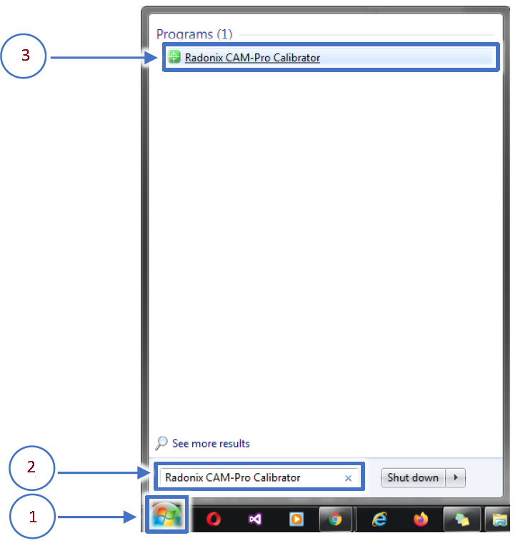
As explained in the previous section, the CAM-Pro Calibrator software is installed alongside the CAM-Pro software. There are two methods to locate the calibrator software after installation. According to the first method, simply go to the installation location, which by default is on the C drive of Windows. Then navigate to the 'Program Files (x86)' folder, open the Radonix folder, and you will find the Radonix CAM-Pro file where the CAM-Pro Calibrator software can be seen. According to the second method, just use the Search feature from the Start menu (Figure 1, Step 1), search for 'Radonix CAM-Pro Calibrator', and run it
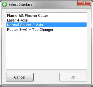
This program consists of two windows. The first window only appears if there are multiple active interfaces on a computer (Figure 3). Through this window, you can select the desired interface and launch it by pressing the 'Ok' button. If there is only one active interface on the computer, the interface selection window will not open, and the main window will open directly.
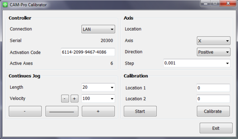
When you open the CAM-Pro Calibrator software, you will see Figure (4), which components are as follows:
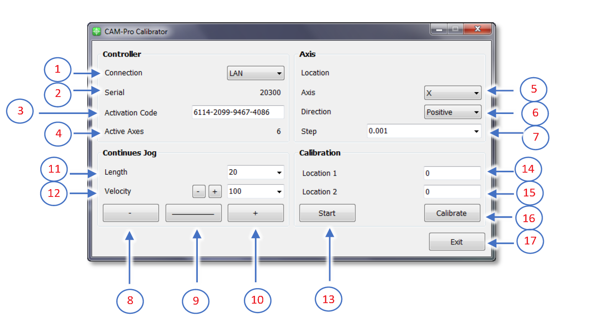
- Connection:
- ProLan controllers must be set to LAN mode.
- ProUSB controllers must be set to USB mode.
- Serial:
- Displays the controller's serial number.
- Activation Code:
- Displays the 16-digit code used to activate axes.
- Active Axes:
- Shows the number of activated axes using the activation code.
Axis Section
5.Axis:
- Allows selecting the desired axis for calibration.
6.Direction:
- Select the appropriate movement direction for standard axes:
- Negative: Movement towards the negative direction.
- Positive: Movement towards the positive direction.
7.Step:
- Sets the step size for calibration or output pulses. After calibration, the step is automatically recorded in the settings.
Continuous Jog Section
8.Negative Jog:
- Enables manual movement in the negative axis direction.
9.Jog Mode:
- Allows selecting the jog movement type:
- Continuous: Smooth, uninterrupted movement.
- Incremental: Moves in defined steps.
10.Positive Jog:
- Enables manual movement in the positive axis direction.
11.Length:
- Defines the incremental movement distance when the Incremental mode is active.
Velocity Section
12.Velocity:
- Used to set the speed for manual movements.
- The positive and negative buttons next to the Velocity option increase or decrease the speed of manual movements.
Calibration Section
13.Start:
- Button to initiate the calibration process.
14.Location 1:
- Used to set the initial position for calibration.
- This position must be relative to a fixed point on the measured axis.
15.Location 2:
- Used to set the final position for calibration.
- This position must also be relative to a fixed point on the measured axis.
16.Calibrate:
- Button to complete the calibration process and calculate the calibration factor.
17.Exit:
- Button to exit the calibration program.
To calibrate an axis, follow these steps:
First, select the desired axis from the Axis section for calibration. Then, by selecting a low speed and moving the axis, ensure the direction of movement is correct. If the movement direction is incorrect, choose the appropriate direction using the Direction section. Next, move the axis to one of the two ends of its travel range. Since the starting direction in this method is not important, it does not matter which end of the axis is chosen as the starting point. Once the axis is in the correct position, measure a point on the axis relative to a fixed point on the machine using an appropriate measuring tool, record this at Location 1, and press the Start button. Note that unit selection is entirely optional, so if calibration with a specific unit is required, all measurements should be based on that unit. For example, the device can be calibrated in units of inches, meters, centimeters, millimeters, or even micrometers.
Move the axis to the opposite end. If measurements at greater distances are possible and the measuring tool is sufficiently accurate, measurements over longer distances will yield more precise results. After moving the axis to the second point, measure this point similar to the first relative to the fixed point on the machine, record this at Location 2, and then press the Calibrate button. Using these measurements, the calibration step or factor is calculated and automatically registered in the designated interface. The calibration process can be repeated as many times as needed for each axis.
Please note that if the activation code has not been entered, an error message will be displayed when opening the CAM‑Pro Calibrator software.
2‑Mathematics Calculation
Computational Method
To align the axis movement with the desired unit, a calibration coefficient called “Step” is used. To access this variable, first open the software and then navigate to the Setting window, proceed to the System branch, and the sub‑branch Axis n (where n represents a number between 1 and 6, indicating the axis number). The Step variable is located within these sub‑branches, and each axis has its own specific Step variable.
If the unit of axis movement is in millimeters, the unit of this variable will be millimeters per pulse. If the movement unit is centimeters, inches, or any other unit, the Step variable will also be expressed in that unit per pulse. Essentially, this represents the amount of movement of the desired axis per one pulse transmitted to that axis’s motor driver. Therefore, to calculate this variable, one must understand the relationship between the motor’s movement amount per input pulse to the driver and the conversion ratios of gearboxes, pulleys, and any other type of motion transmission. For a better understanding of these calculations, consider the following examples:
Example 1: Consider a linear axis of a CNC machine where the measurement unit is in millimeters, and it is equipped with Panasonic A5 motors that have a 10:1 gearbox ratio. This motor is connected via a pinion with an effective diameter of 66 millimeters to a rack. Now, calculate the Step value for the specified axis.
Please note that each piece of information plays a crucial role in these calculations and can be used to compute the step size of the axis for calibration purposes. For example, knowing the type of motor driver and its specifications determines the relationship between the input pulse to the driver and the resulting movement of the motor shaft.
In Panasonic A5 motors, at a rate of 500,000 pulses per second, the motor reaches a speed of 3000 rpm. In the first step, we calculate the motor’s rotational speed per second. Here, the figure 3000 represents the number of motor revolutions per minute, which we convert to seconds by dividing by 60, the number equivalent to one minute. The result is 50, meaning the motor makes 50 rotations per second. Therefore, the equation can be written as: Motor rotational speed per second = 3000 rpm / 60 s = 50 r/s. In the second step, we need to calculate the amount of axis movement per one rotation of the motor.
In fact, in this example, the distance traveled will be equal to the circumference of a circle, and the circumference of a circle is calculated as the diameter of the circle multiplied by π (pi) or approximately 3.1415. As mentioned in Example 1, a pinion with a diameter of 66 millimeters and a 10:1 gearbox are used in the mechanics, so we will have. The amount of axis movement per one revolution of the motor is calculated as (1/10) × 66 mm × 3.1415 = 20.7339 mm. The result obtained is the amount of axis movement per one rotation.
The final step is to write the ultimate equation and find the unknown value, which in this case is the Step variable. As observed, all calculations are based on 500,000 pulses sent by the controller and a motor speed of 3000 rpm. Therefore, to calculate the movement or distance traveled per 1 pulse, the result obtained needs to be divided by 500,000. However, as stated earlier, this motor makes 50 revolutions per second. Thus, it is important to note that while the amount of movement was calculated per 1 revolution in the second step, the motor completes 50 revolutions per second. Therefore, the number obtained in the second step must be multiplied by 50 to find the total distance traveled per second by the motor. Now, we will rewrite the overall equation once more.
Step (mm/pulse) = 50 (r/s) ∗ 20.7339 (mm) / 500000 (pulse/s) = 0.00207339 mm/pulse

From this equation, the Step value is calculated. This value means that the motor moves 0.0207339 millimeters per 1 pulse received.
Please note that the computational method used in Example 1 is intended for the calibration of linear axes.
Step(unit/pulse) = The value of the axis movement per one rotation of the motor * the number of motor rotations per second / Number of pulses sent by the controller per second
Example 2: Consider a rotary axis of a CNC machine where the measurement unit is in degrees. It is equipped with Panasonic A5 motors, which have a 25:1 gearbox connected to a 12-tooth pulley. This pulley is then linked via a belt to a 44-tooth pulley. Now, calculate the Step value for the specified axis.
Motor rotational speed per second = 3000 rpm / 60 s = 50 r/s.
In the final step, we must multiply the effective values, such as the gearbox ratio, the pulley ratio, and the motor's rotational speed per second, by 360. As we observed, all calculations are based on 500,000 pulses sent by the controller and a motor speed of 3000 rpm. Therefore, to calculate the movement per 1 pulse, we must divide the obtained value by 500,000. This simple estimation will yield the Step value.
Step= 50(r/s)∗(1/25)∗(12/44)∗360 / 500000(pulse/s) = 0.000392727272
From this equation, the Step value is calculated.
The general equation for calibrating rotary axes is as follows: Step(unit/pulse) = Rotation amount per second in the motor * effective value * 360 * / Number of pulses sent by the controller per second
Please note that whether calculating linear axes or rotary axes, the more significant digits we use, the more precise the calculation results will be.
Please note Pulse divisions in stepper motors directly impact these calculations. For simplicity, one can first calculate the motor rotation for a specific pulse value and then incorporate the result into the equations above.
Please Note In drives where the number of pulses required to reach the maximum motor speed exceeds the number of pulses produced by the controller, one can achieve the maximum motor speed by increasing the electronic drive ratio to a specific extent. For example, if a drive requires 4 million pulses per second to reach the maximum motor speed, and considering that Radonix produces 500,000 pulses per second, an electronic drive ratio of 8 should be considered to achieve the maximum rotational speed of the motor.
Outputs
In this section, we will examine the configuration of the Outputs.
Setting Up Inputs: General Overview
In Radonix systems, Outports are critical components that manage the output signals controlling various peripherals, such as relays, actuators, alarms, and other devices. Outputs can be categorized into two main types based on their configuration and purpose: Hardware-Based Inputs and Software-Based outputs. This flexibility allows the system to adapt to a wide range of applications and machine requirements.
Hardware-Based Outputs
Hardware outputs involve physical signals sent from the controller to external devices, enabling direct control of the machine’s environment. These outputs are critical for operational safety, machine actuation, and real-time command execution, ensuring efficient workflow and coordination within the CNC system.
The digital outputs of Radonix controllers are named O.[n], where n is a numerical identifier greater than zero and represents the output number .
Radonix controllers incorporate robust protection mechanisms for Outports to ensure durability, safety, and reliability. These mechanisms vary between different models, specifically the PC-Pro and PC-Smart boards, each with distinct protection features and failure handling processes.
Output Behavior in PC-Pro LAN Models
- The PC-Pro LAN model outputs are fixed in NPN mode.
- How It Works:
- When an output is ON, it provides 0 volts by pulling the signal to ground.
- When an output is OFF, it is in a high-impedance state, effectively disconnecting the circuit.
- Wiring Consideration:
- Connected devices must be compatible with NPN logic, where the load receives voltage from a positive source and is activated when the output pulls the circuit to ground.
2. Output Behavior in PC-Smart Models
- The PC-Smart model offers a flexible configuration where outputs can operate in PNP mode or NPN mode, depending on the connection of the COM Pin.
- How It Works:
- The voltage provided by the outputs depends on what is connected to the COM Pin:
- COM Pin Connected to 24V: Outputs will provide 24 volts when activated.
- COM Pin Connected to Ground: Outputs will provide 0 volts when activated (NPN mode).
- The voltage provided by the outputs depends on what is connected to the COM Pin:
- Flexibility:
- This design allows PC-Smart models to adapt to different wiring requirements and device logic preferences.

Configuration Process for Outputs:
- Connection:
- Physically connect the hardware component (e.g., relay, electric valve , Barke , alarm) to the designated output pin on the controller.
- Ensure proper wiring based on the required logic (PNP or NPN) and voltage compatibility.
- Output Definition:
- Use the controller software to define the role of the output (e.g.,
C-CutPin,Brake, or a custom output for specific functions). - Assign the output to its intended device or operation in the system settings.
- Use the controller software to define the role of the output (e.g.,
- Logic Settings:
- Set the output logic based on the connected device's requirements:
- Active High (PNP): The output sends voltage (e.g., 24V) when activated.
- Active Low (NPN): The output pulls the signal to ground (0V) when activated.
- Set the output logic based on the connected device's requirements:
- Testing and Validation:
- After configuring, test the output to ensure it operates as intended in CAM Pro Test application.
- Use a multimeter or other diagnostic tools to verify output voltage and behavior.
2. Software-Based Outputs
Software-Based Outputs provide simple logical functionality to configure and integrate them with related physical hardware. These features are crucial for enhancing control capabilities. They facilitate quick and simple installation without the need for microprogramming. Users can simply select options from a list and configure settings to maximize efficiency.

As illustrated in the figure, each output is divided into three sub-branches, as detailed below:
- Enable: This sub-branch can be set to two values: True or False.
- Link: Specifies the duty or task that needs to be performed or checked. This includes any device that can serve as an output, such as actuators, lights, and alarms.
- NC: Determines whether the specific output is Normally Open (NO) or Normally Closed (NC).
Examples of Software Outputs:
- Virtual Relays:
- Use software parameters to define activation boundaries for devices based on operational needs.
- Logical Triggers: Define conditional triggers for activating specific outputs (e.g., alarms or Relay for specific function ).
- Simulated Outputs: Employ these for testing or in scenarios where physical components are not available.
Configuration Process:
- Access the Configuration Interface:
- Navigate to the controller's software settings to manage outputs.
- Define Parameters:
-
To configure an output like an order to forward the VFD, enter parameters.
-
setting —→ System —→ Outports —→ Enabled= True
Linked = C-CutPin
NC= True
-
- Validate Settings:
- Test the configured software outputs to ensure they function correctly and safely, verifying their effectiveness in real-world applications.
Setting Up Inputs: Simple and Intuitive Configuration
In Radonix system, configuring inputs or Outputs is designed to be as user-friendly as possible, without requiring any microprogramming or advanced technical knowledge. All you need to do is navigate to the Inputs section of the controller interface, open the settings drawer, and select the item you need to configure. The same process applies to other sections, such as Outputs or any other functional areas.
Step-by-Step Configuration Process
- Access the Desired Section:
- Go to the section you want to configure, such as Inputs or Outputs, depending on the functionality you are setting up.
- Open the Settings Drawer:
- Within the selected section, locate the specific input branch or subsection.
- Click or expand the settings drawer to reveal the available options.
- Select the Required Item:
- Choose the input type or functionality you want to configure (e.g., limit switch, home sensor, emergency stop, or custom inputs).
- Define the specific role for the input, such as
C-ZFreePin,1
- Set Parameters Easily:
- Adjust the necessary parameters, such as polarity (Normally Open or Normally Closed), response delays, or logical behavior, directly from the interface.
- Save and Test:
- Save your settings and validate them through the controller interface to ensure everything is functioning as intended.
- In the end in order to finalizing you have to close program to save everything
Certain inputs and outputs in a CNC machine are fundamental for its proper operation and safety. These links are vital for controlling key components like torch, motors, sensors, and safety mechanisms. Additionally, there are other links that, while not critical, enhance functionality and provide added convenience. These will be explained further in this section.
Functions
Functions are commands that can be invoked and executed in various ways (digital input definition, software screen button definition, M-Code definition, remote or keyboard button definition, etc.). Each function includes a number of arguments that determine the type of operation it performs. The functions of the Cutter interface include the following:
Cut-C: Used to enable or disable the C-CutPin output, which includes the following arguments:
➢ W-Cut,0: Invoking this function deactivates the C-CutPin output.
➢ W-Cut,1: Invoking this function activates the C-CutPin output.
➢W-Cut,2: Each invocation of this function toggles the state of the C-CutPin output from off to on or from on to off (operates as a toggle).,
W-ManualCut In Cutter interfaces, operators have the capability to run the loaded design once in Demo mode without activating the cutting output and at high speed (the speed for this mode can be adjusted from the Setting→System→ToolPath→TraverseVelocity section). This allows operators to ensure the correct execution of the design and that the entire cutting path is properly aligned with the raw material. To activate this mode, we use the C-ManualCut function, which includes the following arguments:
➢W-ManualCut,0: Invoking this function deactivates the Demo mode.
➢ W-ManualCut,1: Invoking this function activates the Demo mode.
➢ W-ManualCut,2: Each invocation of this function toggles the Demo mode between active and inactive (functions as a toggle). Functions
Functions are commands that can be invoked and executed in various ways (digital input definition, software screen button definition, M-Code definition, remote or keyboard button definition, etc.). Each function includes a number of arguments that determine the type of operation it performs. The functions of the Cutter interface include the following:
Inports :
W-Cutsensorpin : If this input is defined, the device will pause after the output C-CutPin is activated and wait for this input to be activated. Immediately after this input is activated, the device will continue the cutting process. The presence of the word 'sensor' in the name of this input does not necessarily mean that there is a sensor to detect the completion of the Cut process. This input could be a push button that the operator can press to activate it.”
W-PreCutSensorPin : If this input is defined, the device will pause after the output C-CutPinPre is activated and will wait for this input to be activated. Immediately after this input is activated, the device will resume the cutting process. As explained above, the presence of the word 'sensor' in the name of this input does not necessarily imply the existence of a sensor for detecting the completion of the PreCut process. This input could be a push button that the operator can press to activate it.
Outputs :
W-PreCutPin: This is the initial or pre-cut output that activates after the device reaches the cutting point. If the input C-PreCutSensorPin is defined in the inputs section, the output remains active until this input is activated and deactivates upon activation of C-PreCutSensorPin. If C-PreCutSensorPin is not defined, this output deactivates after a duration determined by the PreCutTime parameter and proceeds to the next stage. In this case, the operator can bypass the pre-cut timing by invoking the C-Cut function (pressing the Cut button) and enter the cutting stage directly.
W-CutPin : This is the second stage output or cutting output, which becomes active after the completion of the first stage, but the device does not move. After this output is activated, if the input C-CutSensorPin is defined in the inputs section, the device will start moving and perform the cutting operation upon activation of this input. If C-CutSensorPin is not defined, the device will start moving and perform the cutting operation after a duration determined by the C-CutTime parameter. In this case, the operator can bypass the cutting timing by invoking the Run function (pressing the Play or Start button) and begin moving along the cutting path.
W-PreCutPin+W-CutPin: This output is active when either the CutPin-C or PreCutPin-C outputs are active. If both outputs are deactivated, this output also deactivates.
W-PostCutPin: This output is activated immediately after the cutting process is completed and the CutPin-C output is deactivated. The device stops at that point. After a duration determined by the C-PostCutTime parameter, the device starts moving again and proceeds to the next point to begin cutting.
W-PompPin,1 :
Activates the low-pressure mode of the water jet system, allowing for operations that require water flow without the high pressure used for cutting. This mode is often used for setting up or cleaning the cutting area.
The Radonix CAM-Pro software interface features a dedicated button for directly enabling and disabling the Low Pressure (LP) output. This button provides operators with immediate control over the LP system, crucial for managing operations without navigating through multiple menus.
W-PompPin,2 =
Activates the high-pressure mode of the water jet system, allowing for operations that require water flow without the high pressure used for cutting. This mode is often used for setting up or cleaning the cutting area.
The Radonix CAM-Pro software interface features a dedicated button for directly enabling and disabling the High Pressure (HP) output. This button provides operators with immediate control over the HP system, crucial for managing operations without navigating through multiple menus.
W-AbresivePin =
Control the Abrasive Feeder in Radonix CAM-Pro using this output link. Additionally, a button on the interface allows for direct control of the feeder.
Water Jet
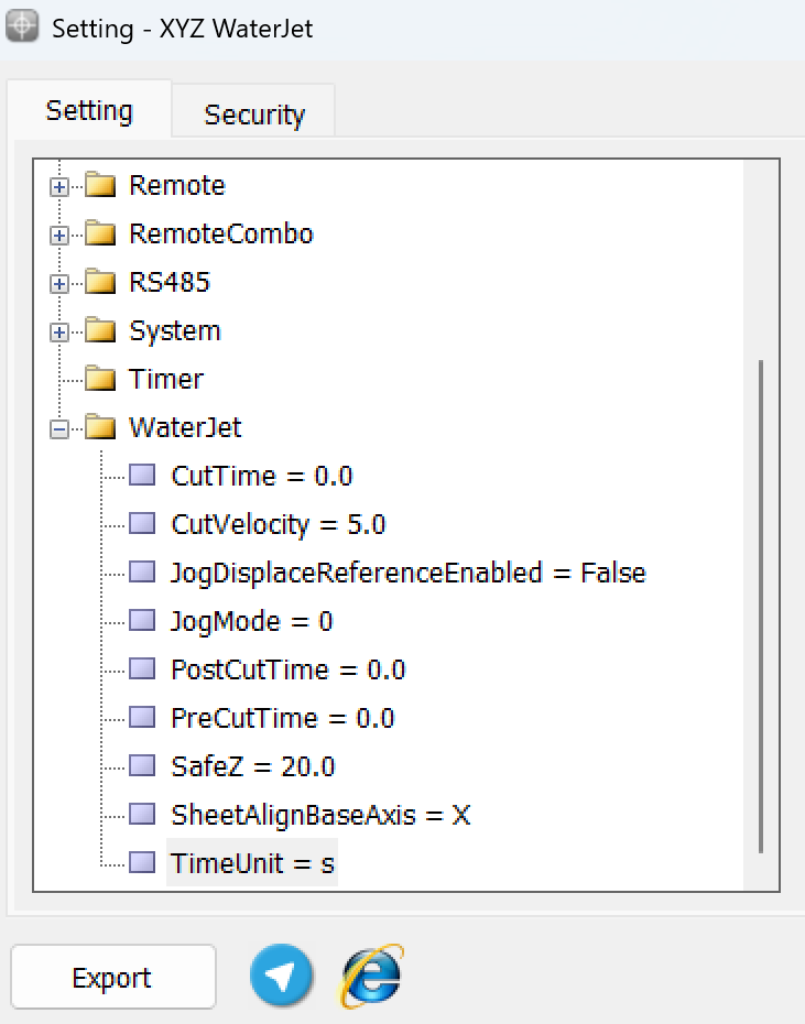
CutTime: If the input CutSensorPin-C is not defined and the parameter TrueAutoCut= is set to true, the device will pause for the duration specified in this parameter after the output C-CutPin is activated, and then it will begin cutting the piece. The unit of this parameter is determined by the TimeUnit parameter.4
CutVelocity: If the operator needs to manually cut a part of the piece without a cutting plan, this can be achieved by activating the output C-CutPin and using the manual movement keys (JOG). Under these circumstances, the movement speed of the device is determined by this parameter, which is measured in millimeters per second (mm/s).
JogDisplaceReferenceEnable: If the value of this parameter is set to True, in addition to the Continuous mode for manual movement of the device, a third mode is added which is determined by Step. In this mode, the reference position or zero of the workpiece will shift by the same amount as the device's movement. If the value of this parameter is set to False, this mode will no longer be displayed. It is worth mentioning that the Type parameter of this button, unlike other interfaces, is of the Button type and not a Toggle.
JogMode: In interfaces where JogDisplaceReference mode exists, to ensure that the manual movement mode, or JogMode, is saved and does not revert to the default setting (Continuous mode) in subsequent software executions, a parameter has been included in the settings to store this mode. Therefore, this parameter does not require special configuration.
PostCutTime: This parameter determines the duration of the device's pause after the completion of a cut and the deactivation of the C-CutPin output before moving to the starting point of the next piece to be cut. The unit of this parameter is specified by the TimeUnit parameter.
PreCutTime: If the input CutSensorPinPre-C is not defined and the parameter TrueAutoCut= is set to true, the device will pause for the duration specified in this parameter after the C-PreCutPin output is activated, and then it will activate the C-CutPin output. The unit of this parameter is specified by the TimeUnit parameter.
SheetAlignBaseAxis: This parameter identifies the base axis for calculations related to Sheet Align. More detailed information about this parameter will be provided in the Sheet Align section.
TimeUnit: This parameter specifies the unit for time-related parameters. 'ms' stands for milliseconds, and 's' stands for seconds.
Sheet Align
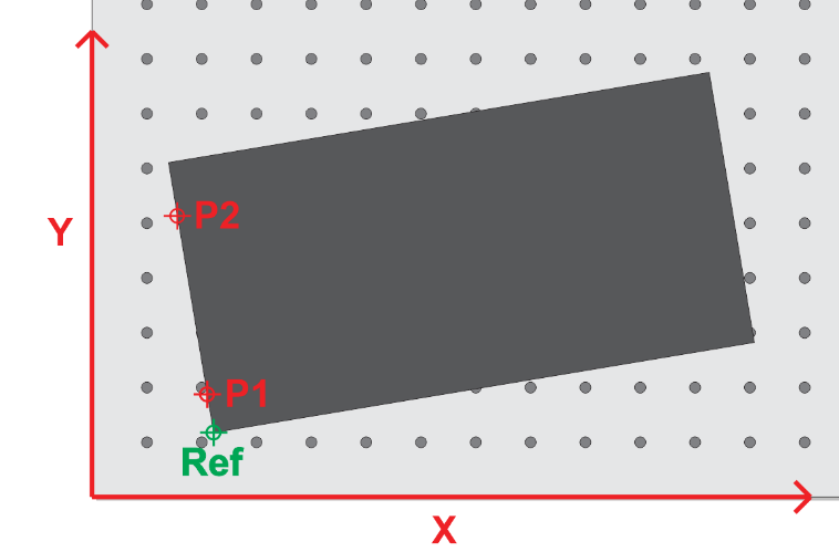
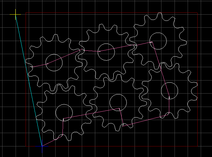
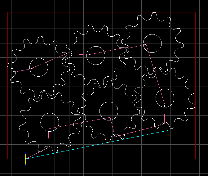
When placing the workpiece on the cutting table of the machine, there may be conditions that prevent aligning the piece with the motion axes (the workpiece may be placed askew or, in technical terms, not squared).
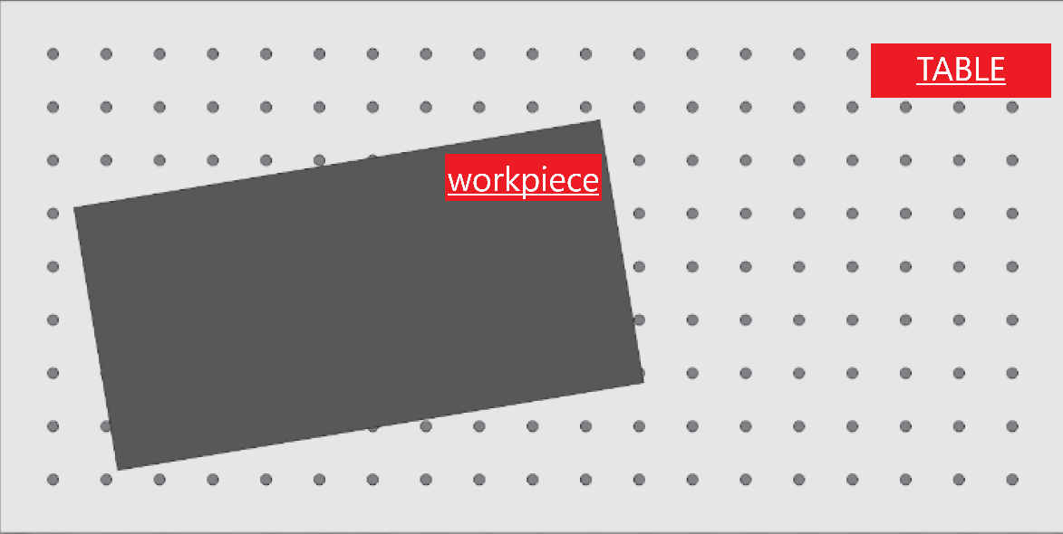
In these circumstances, it is necessary for the loaded design to rotate around the zero point according to how much the workpiece is skewed relative to the cutting table, so that the design aligns with the workpiece. To calculate the amount of rotation needed for the design, two points on the workpiece must be introduced to the software as shown below, allowing the software to compute the angle of rotation.
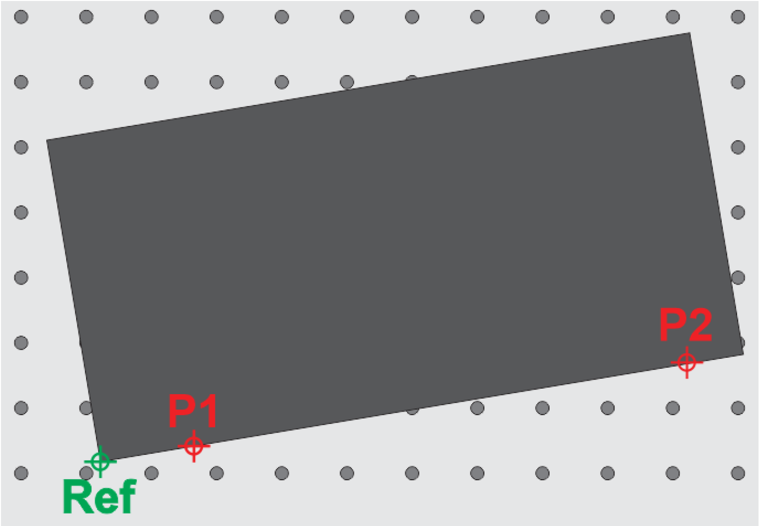
For this task, after loading the desired design, the cutting nozzle tip should be brought to a point tangent to the edge of the sheet. At the first point, press the P1 button, and at the second point, press the P2 button to introduce these two points to the software. By doing this, a blue line is drawn between these two points, which is exactly tangent to the edge of the workpiece.
After that, by pressing Sheet Align, the design becomes tangent to the blue line and is completely pos.

It should be noted that the greater the distance between the two points P1 and P2, the more accurately this process will be performed. Now, we will have one of the following two scenarios:
SheetAlignBaseAxis=X: In this scenario, the points are selected along the X-axis, and the loaded design will align with the line connecting the two points P1 and P2 (as illustrated below):
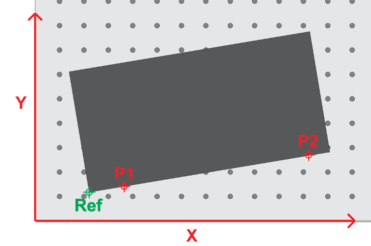
SheetAlignBaseAxis=Y: In this scenario, the points are selected along the Y-axis, and the loaded design will align with the line connecting the two points P1 and P2 (as illustrated below )