Add Item
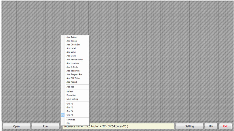
Interface Editing Environment – Context Menu (Empty Area)
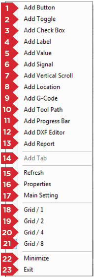
When you right-click on an empty area in the interface editor, the menu shown in Figure 27 appears.
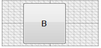
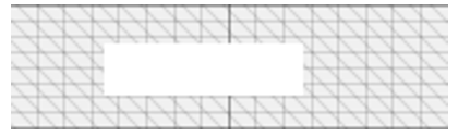
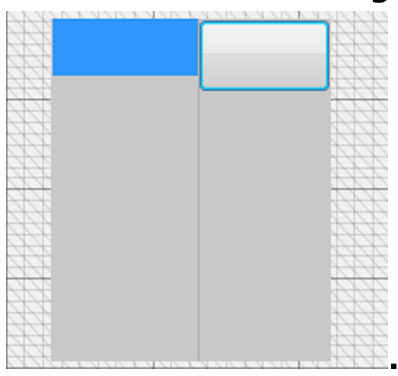
1. Add Button
In the editor, a Button looks like this:
Right-click a Button → Properties to open its settings window.
See Properties for a full list of Button properties.
Link
- Value
- Analog
- Function
- OutPort
- InPort
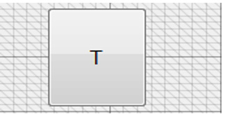
2. Add Toggle
Use for two-state commands (on/off). Toggles flip their linked function each click (e.g. spindle on/off).
Right-click a Toggle → Properties to edit.
See Properties.
Link
- Value
- Analog
- Function
- OutPort
- InPort
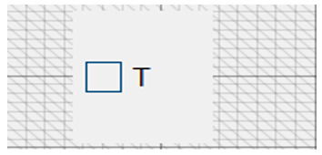
3. Add Check Box
Also two-state. Checked = output on; unchecked = off (e.g. vacuum on/off).
Right-click a Check Box → Properties.
See Properties.
Link
- Value
- Analog
- Function
- OutPort
- InPort
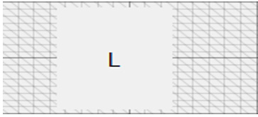
4. Add Label
Displays static text or a read-only variable (e.g. current feed rate).
Right-click a Label → Properties.
See Properties.
Link
- Value
- Analog
- Function
- OutPort
- InPort
5. Add Value
Displays and allows editing of a numeric variable.
Right-click a Value → Properties.
See Properties.
Link
- Value
- Analog
- Function
- OutPort
- InPort
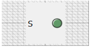
6. Add Signal
Shows a Boolean state (True/False) with three color variants.
Right-click a Signal → Properties.
See Properties.
Link
- Value
- Analog
- Function
- OutPort
- InPort
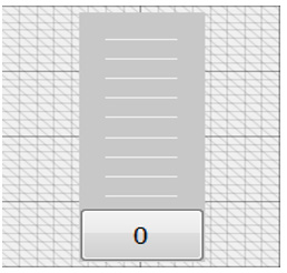
7. Add Vertical Scroll
Use for adjusting numeric parameters (e.g. feed rate).
Right-click a Vertical Scroll → Properties.
See Properties.
Link
- Value
- Analog
- Function
- OutPort
- InPort
Add Location
Shows axes coordinates in Absolute or Relative modes.
8. Add Location
Displays axis positions:
- Absolute: relative to Home
- Relative: relative to the current Reference point

Right-click a Location → Properties.
See Properties.
9. Add G-Code
Displays the loaded G-code file and highlights executed lines in real time.
Right-click G-Code → Properties.
See Properties.
10. Add Tool Path
Shows the machining simulation or actual toolpath, with work size and length, and 3D view controls.
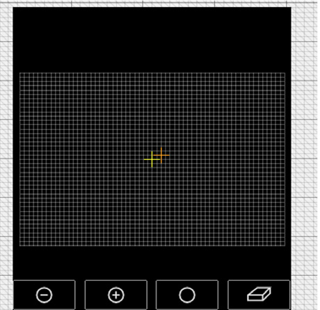
Right-click Tool Path → Properties.
See Properties.
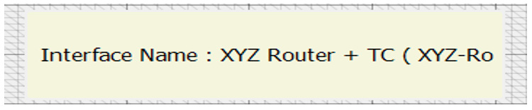
11. Add Progress Bar
Displays:
- Interface name
- Elapsed/remaining time during operations
- Alarms in red
- Double-click → Debug Form
- Ctrl+Shift+Alt+PrtSc twice → performance report in Notepad
Right-click Progress Bar → Properties.
See Properties.
12. Add Tab
Creates a new tab/page. Only available from the bottom toolbar.
Right-click Tab → Properties.
See Properties.
13. Refresh
Reloads or updates the display (e.g. after changing a property).
14. Properties
Opens the settings window for any selected element.
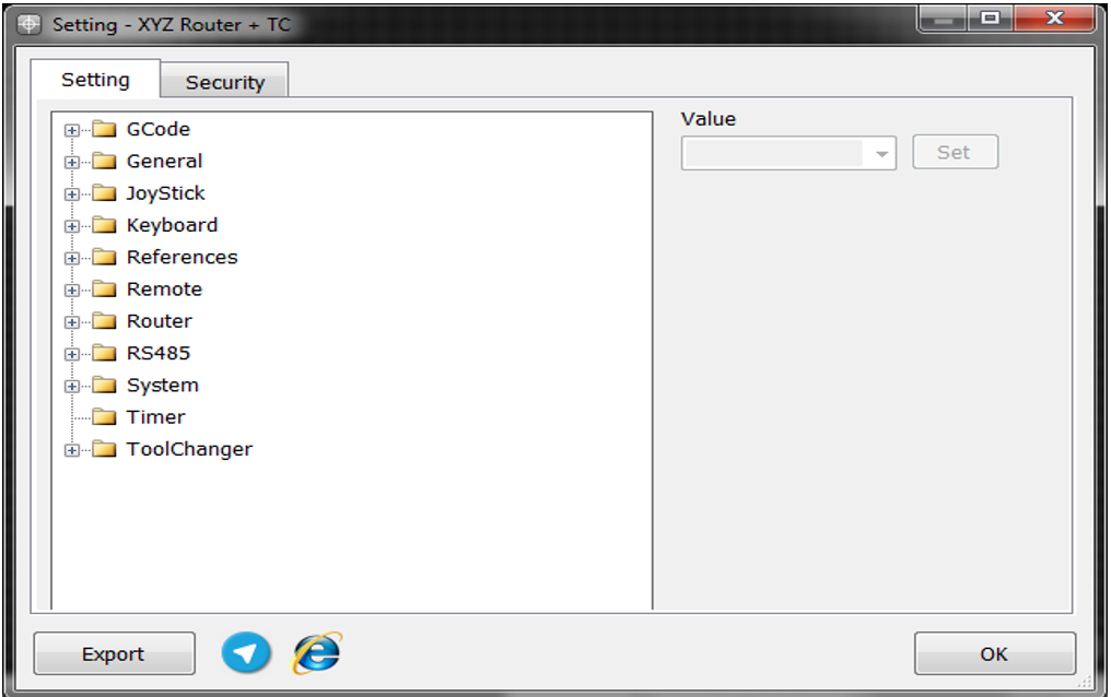
15. Main Setting
Opens the Settings dialog with Setting and Security tabs, plus links to Radonix Telegram and website.
16–19. Grid Levels
Control move snapping precision:
- Grid / 1: coarse
- Grid / 2: 2× finer
- Grid / 4: 4× finer
- Grid / 8: 8× finer


20. Minimize
Minimizes the editor window.
21. Exit
Closes the interface editor.