Step-by-Step Guide
Installation and Setup Process for Radonix CNC Controller
Radonix recommends following this detailed step-by-step guide for installing and configuring a Radonix CNC controller. The process encompasses everything from wiring the hardware to setting parameters in the software. This approach aims to guarantee a seamless installation experience for customers, addressing all critical components.
Wiring Components for a Radonix CNC Controller
Proper wiring is the foundation of a reliable and high-performing CNC machine. A professional approach to wiring ensures seamless communication between the Radonix controller, servo or stepper motors, sensors, VFDs (Variable Frequency Drives), and other peripherals. This guide provides expert advice on wiring all components, including selecting appropriate power supplies, ensuring safety, and achieving optimal performance.
1. Main Components Overview
A typical CNC system includes the following components, all of which require precise and secure wiring:
- Radonix CNC Controller: The central control unit.
- Servo or Stepper Motors: Responsible for axis movement.
- Variable Frequency Drive (VFD): Controls the spindle motor.
- Sensors:
- Home Sensors for axis referencing.
- Limit Switches for boundary control.
- Home Sensors for axis referencing.
- Limit Switches for boundary control.
- Emergency Stop (E-Stop): Ensures immediate shutdown during emergencies.
- Power Supplies: Provides regulated power for different components.
- Peripheral Outputs: Includes relays, coolant pumps, and alarms.
2. Wiring the Main Power Supply
Choosing the suitable Power Supply
-
Controller Power Supply:
It is recommended to use 24V switching power supplies to power the Radonix controllers. Calculating Power Supply Current To determine the required power supply current in the electrical panel, the current consumption of each element connected to the power supply must be calculated. For example, if there are 4 relays, 3 pneumatic solenoid valves, and a controller in a switchboard, the current consumption can be determined using Ohm’s law (V=I*R). The electric currents should be calculated and their sum considered as the current of the power supply, along with a confidence factor of a few percent. For example, if the current consumption of the relays is 0.1A and that of the solenoid valves is 0.25A, the total current can be calculated as follows: Total current = controller current + relay current + solenoid valve current IT = 0.5 + 4 * 0.1 + 3 * 0.25 = 1.65A
3. Anti-Noise Measures for CNC Wiring
Electromagnetic interference (EMI) or electrical noise is a common issue in CNC systems, particularly when wiring sensitive components like controllers, servo drives, and sensors. Noise can disrupt signals, cause erratic machine behavior, and even damage components over time. Implementing robust anti-noise measures is critical for ensuring the reliable and precise operation of your CNC machine.
Sources of Electrical Noise
- High-Frequency Devices:
- Variable Frequency Drives (VFDs)- (In Related Machines)
- Switching power supplies
- High-Power Components:
- Spindle motors - (In Related Machines )
- Servo and stepper motors
- Long Cables:
- Longer cables act as antennas, picking up EMI.
- Proximity to Power Lines:
- Signal and power cables running close together can cause interference.
Key Anti-Noise Measures
1. Use Shielded Cables
- Purpose: Shielded cables reduce the effect of electromagnetic interference on sensitive signals.
- Implementation:
- Use twisted-pair shielded cables for signal lines like Pulse+, Pulse-, Direction+, Direction-, and sensor signals.
- Connect the shield to ground at one end only to avoid ground loops.
2. Separate Signal and Power Cables
- Purpose: Prevent high-power cables from inducing noise in low-power signal cables.
- Implementation:
- Route signal cables (e.g., sensor and control signals) separately from power cables (e.g., motor power and VFD output).
- Maintain at least 10-15 cm of separation between these cable types.
- Use different cable trays or conduits for power and signal lines.
3. Proper Grounding
- Purpose: A well-designed grounding system minimizes noise and protects components.
- Implementation:
- Create a central grounding point in the electrical box, often referred to as a grounding bus bar.
- Ensure all grounding wires (controller, drives, motors, etc.) connect to this central point.
- Avoid daisy-chaining ground connections, which can introduce noise.
4. Install Ferrite Beads
- Purpose: Ferrite beads filter out high-frequency noise on signal and power cables.
- Implementation:
- Clip ferrite beads onto signal and control cables near the controller or servo drives.
- Use multiple beads for particularly noisy environments.
5. Proper VFD Wiring
- Purpose: VFDs are a significant source of electrical noise and require special attention.
- Implementation:
- Use shielded cables between the VFD and spindle motor.
- Ground the cable shield at the VFD end.
- Install line filters or chokes on the VFD input and output to suppress noise.
6. Shorten Cable Lengths
- Purpose: Longer cables are more susceptible to picking up noise.
- Implementation:
- Keep cable lengths as short as possible without compromising flexibility.
- Avoid unnecessary slack or loops in the wiring.
7. Use Isolated Power Supplies
- Purpose: Prevent noise from one system affecting another.
- Implementation:
- Use separate, isolated power supplies for sensitive components like sensors, encoders, and the controller.
- Ensure power supplies are adequately rated and properly grounded.
8. Use Optical Isolation
- Purpose: Protect the controller from noise on external connections.
- Implementation:
- Use opto-isolators for connections to external devices like sensors, relays, or switches.
- Many Radonix controllers have built-in optical isolation for inputs and outputs.
9. Secure Connections
- Purpose: Loose connections can act as noise sources.
- Implementation:
- Check all connectors for tight and secure connections.
- Use locking connectors where possible to prevent accidental disconnections.
10. Line Filters and Surge Protectors
- Purpose: Suppress high-frequency noise and protect against voltage spikes.
- Implementation:
- Install EMI line filters on the AC mains supply.
- Use surge protectors on power inputs to the controller and VFD.
Software Configuration: Bringing the System to Life
Step 1: Install Radonix Cam Pro
- Download and install the software on your PC.
- Upon turning on the controller, observe the LEDs on the LAN port: one should remain steady, while the other blinks.
- Connect the Radonix controller to the computer via a LAN or USB cable.
Step 2: Initial Setup
- Open the software and initialize the system.
- Perform a factory reset to ensure default settings are applied.
Step 3: Configure Inputs
- Navigate to Settings > System > Inports.
- Assign roles to each input:
EmergencyStopfor the E-Stop button.HomePin, X/Y/Zfor home sensors.LimitPin, X/-Xfor limit switches.
- Test each input by activating it physically and observing the software response.
Step 4: Configure Outputs
- Navigate to Settings > System > Outports.
- Assign roles to each output:
C-CutPinfor turn on torch.C-ZfreePin,1for active a Relay to move axis Z upward .C-ZfreePin,-1for active a Relay to move axis Z downward .
- Test outputs by toggling them in the software and observing the connected devices.
Step 5: Axis Calibration
- Go to Settings > System > Calibration.
- Enter parameters for each axis:
- Steps per Unit: Based on lead screw pitch, motor steps, and encoder resolution.
- Max Travel: Define the maximum travel distance for each axis.
- Test calibration by commanding movements and measuring actual travel distances.
Introduction
So here we have an interface which is related to Radonix CNC controllers in this software application there are some different outputs and inputs links in this part I provide a Text and illustration about the relation between these inputs and Outputs to create and flowchart and algorithm to easier install and run this application .
This interface is called XYC Simple Glass Cut that includes kind of CAM which is called SimpleCAM or S-CAM
Study about different part of interface which is named and indicated in photo it means that you should get familiar with all elements like Buttons , screen , bars , volume , values , … anything on interface you have accesses
XYC Simple Glass Cut
For starting primary installation there are some steps to go throw it and has a successful installing
Get Start
Workspace Descriptions
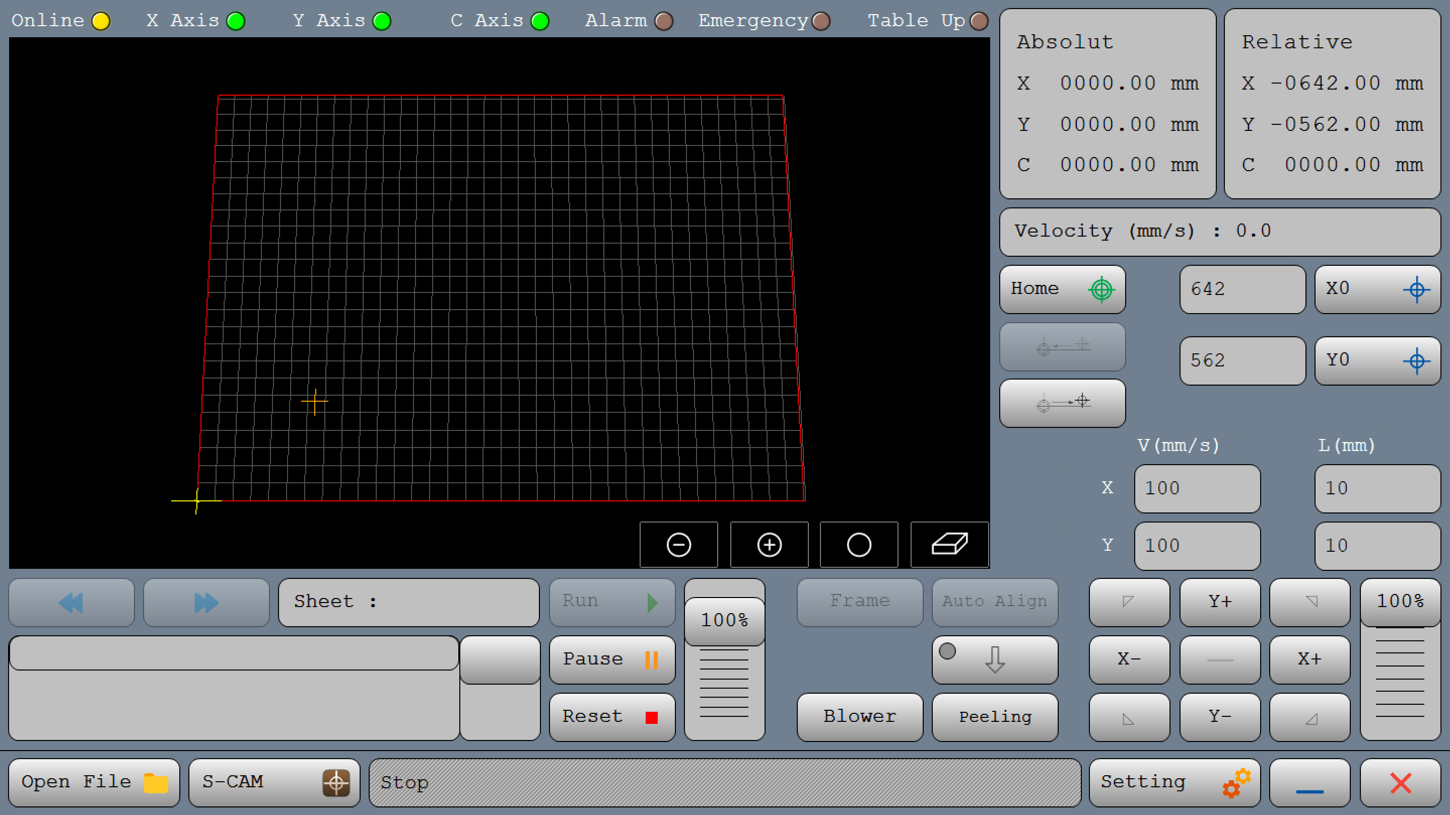
Here's a detailed description of each section and button on this CNC controller interface
Top Status Bar

- Online (Yellow Light): Indicates the machine's connection status. If the controller and software are connected, it is on.If there is no communication between the controller and the software, it will be turned off or displayed in gray color.
- X Axis, Y Axis, C Axis (Green Lights): These lights show the operational status of each axis. Green typically means these axes are active or ready.
- Alarm, Emergency, Table Up (Brown Lights): Indicators for critical safety statuses. When activated, they may change color (e.g., red) to signal an alarm, emergency stop, or table positioning issue.
Position and Speed Readouts (Right Panel)
- Absolute Position (Top Right Box):
Absolute: Displays the coordinates of the axes in reference to thehome point.
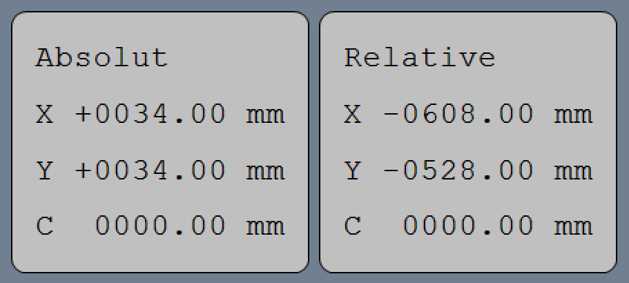
- Relative Position (Besides Absolute Position):
Relative : Shows the coordinates of the axes relative to thereference point.
- Velocity (Below Relative Position): Shows the current operational speed in mm/s, useful for monitoring real-time cutting or movement speeds.

Position Controls (Mid Right Panel)
-
Home (Target Icon): Moves the machine to its home or origin position.

-
X0 and Y0 (Crosshair Icons): These buttons take spindle to the X and Y coordinates to zero or move the tool to the zero point in each axis.
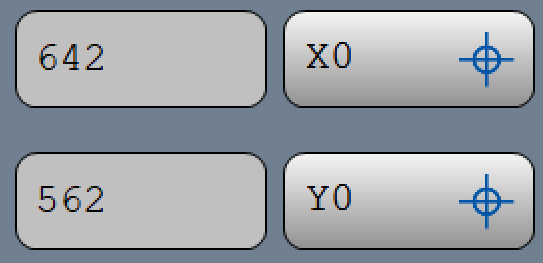
-
You have two options for saving reference points. The first option is to manually move the tool by jogging, and when you reach the desired point, press the corresponding button to save that position for the axis. The second option is to directly enter the precise position value in the input box in front of each button.
Manual Jogging Controls
- Arrows (X+, X-, Y+, Y-): These buttons manually jog the machine along the X and Y axes, allowing for precise positioning adjustments by moving the tool head incrementally.
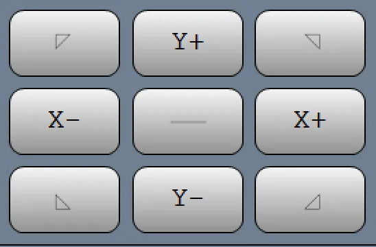
- You can switch the jog mode by pressing this button according fig 01-05 and it will change to figure 01-06, changing from continuous to incremental movement. This means you can define a value in this section according fig 01-07 which has been indicated in red area , and after pressing the coordinate axis jog, the axis will move by the amount you have entered.

Figure 01-05

Figure 01-06
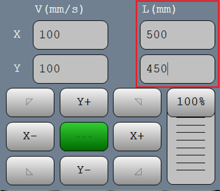
Figure 01-07
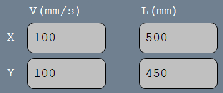
Feed Rate and Tool Parameters (Lower Right Panel)
-
V (mm/s) and L (mm): Input fields for setting feed rates and movement limits along each axis. "V" controls the velocity (or speed) in mm/s, and "L" could define the step size for each manual jog.
-
Scroll (Vertical Slider on Bottom Right ):According to figure 01-08 which is demarcated with red area or Allows for real-time adjustment of the feed rate or speed as a percentage. This control can quickly change the speed without directly altering program values.
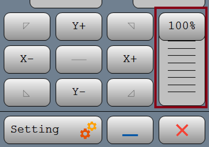
Main Program Controls
- Settings (Gear Icon): Opens the configuration menu, where detailed settings for the CNC machine can be adjusted.

- The Exit icon allows you to close the program
- The Minus icon lets you minimize it.
Interface specification :

This section of the interface displays the current status and features of the system. It also updates to show alarms and processes every second. For a detailed report, double-click on this section.
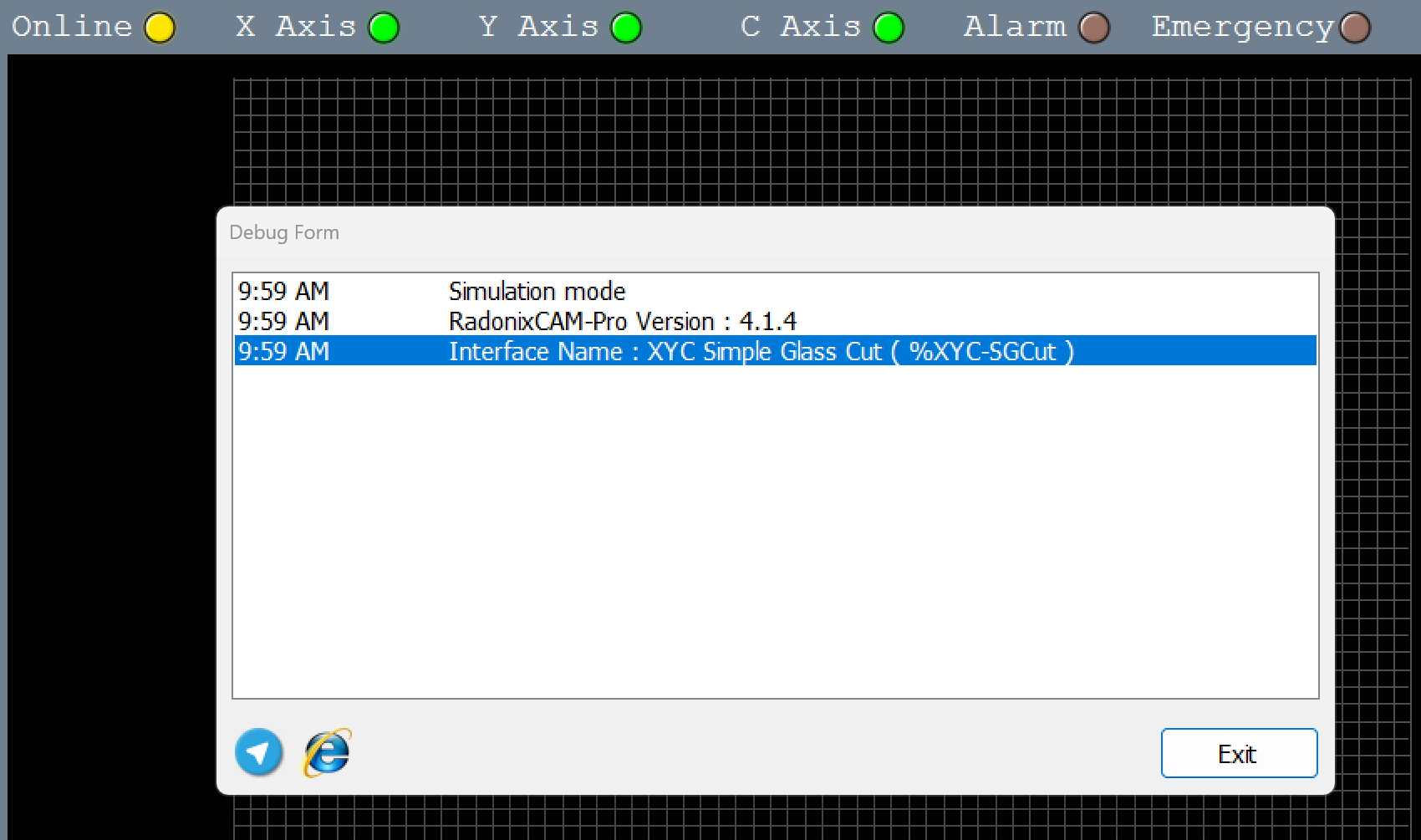
In this image the interface had been in @simulation mode
Main Program Controls (Bottom Center)
- Open File (Folder Icon): Opens a file dialog for loading a CAM (Computer-Aided Manufacturing) file, typically a G-code or DXF program.
- S-CAM: This may open a specific CAM software interface or display related options for configuring a machining job.
Special Functions (Lower Right Buttons)
- Frame (Gray, Possibly Disabled): Frames or shows the cutting area, outlining the path that the tool will follow.
- Auto Align (Gray, Possibly Disabled): Could automatically align the glass sheet based on your design.
- Blower: Activates the air blower to facilitate the movement of glass sheets. .
- Peeling: This could activate a peeling function, used for removing any protective covering (like paper) from the material surface before processing.
This section is dedicated to controlling G-Code execution:
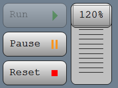
- RUN: This button starts the G-Code process.
- Pause: This button halts the toolpath.
- Reset: This button resets the toolpath.
Display and Zoom Controls (Center of Main Display)
- Grid Display (Black Area with Grid): Shows the work area and toolpath visualization. The grid assists in visualizing the relative position of the tool and workpiece.
- Zoom and Pan Controls:
- + and - Buttons: Zoom in and out on the display.
- Hand Icon: Allows panning across the display grid.
- Other Icons (Bottom Right of Grid): These might control additional viewing or display settings, such as full screen or different zoom presets.
Glass Branch
Loader Down Delays
This parameter is crucial for managing how glass sheets are deposited back onto a surface or into a new position .The "Loader Down Delay" serves a parallel purpose during the lowering or placement phase.
Understanding Loader Down Delay
1. Purpose of Loader Down Delay:
- Controlled Descent: This delay regulates the speed and timing of lowering the glass to ensure that it is placed gently and precisely. It prevents any sudden drops that could crack or shatter the glass.
- Stabilization: Allows the machinery and the glass to stabilize before final placement, ensuring that the glass is perfectly aligned according to the operational requirements.
2. Implementation and Benefits:
- Enhanced Safety: By controlling the descent, loader down delays minimize the risk of damage to both the glass and the machinery, enhancing operational safety.
- Improved Accuracy: Slowing down at critical moments allows for finer adjustments in positioning, which is especially important for complex assemblies or delicate glass types.
- Operational Efficiency: While introducing a delay might appear to slow the process, it actually enhances efficiency by reducing the likelihood of errors and the subsequent need for rework or glass replacement due to damage.
Loader Up Delays
Loader Up Delays in Glass Sheet Handling
The term "Loader Up Delays" refers to the timed intervals that are crucial when using mechanical loaders to handle glass sheets, particularly in settings where CNC machines are employed for cutting or processing. These loaders can be hydraulic (hydric) or pneumatic, and each type has its unique characteristics and operational requirements.
Hydraulic Loaders:
- Functionality: Hydraulic systems utilize fluids to generate the force needed to lift and move heavy glass sheets. These systems are known for their smooth and powerful operation.
- Delay Significance: Delays in hydraulic systems may occur as the fluid pressure builds up to the required level for operation. These delays are crucial for ensuring that the movement starts smoothly and that the glass is handled safely without abrupt movements that could lead to damage.
Pneumatic Loaders:
- Functionality: Pneumatic loaders use air pressure to operate. They are generally faster than hydraulic systems but might not provide the same level of force.
- Delay Significance: In pneumatic systems, delays might be used to control the rapid response time of air pressure build-up, ensuring that the glass sheets are not subjected to sudden jolts, which could cause cracks or breaks.
Operational Considerations:
- Safety: Delays are programmed to ensure that the load is securely held before movement starts, preventing slippage or misalignment.
- Efficiency: Properly timed delays contribute to the operational efficiency of the loading/unloading process, allowing for seamless transitions and minimizing the risk of mechanical failures or glass damage.
Adaptability Across Models:
- Different models of loaders, whether hydraulic, pneumatic, or other types, can have varied settings for these delays depending on the machine design, the weight of the glass sheets, and the specific requirements of the operation.
In industrial settings where precision and safety are paramount, understanding and setting these "Loader Up Delays" correctly is essential. They ensure that the machinery operates within safe parameters while maintaining efficiency and protecting the materials being handled. This careful balancing of delay times helps optimize the overall workflow and extends the lifespan of both the mechanical loaders and the glass materials they handle.
In the context of handling glass with loaders that feature intensive movements, having dual parameters for "Loader Up Delays" is particularly important. These parameters are specifically designed to manage and mitigate the risks associated with the rapid and forceful movements of the loader, ensuring both safety and precision during operation.
Importance of Managing Intensive Movements
1. Reducing Mechanical Stress:
- Rationale: Intensive movements can generate significant mechanical stress on both the glass and the machinery. By implementing strategic delays, these stresses can be controlled, reducing the potential for mechanical failure or damage to the glass.
- Implementation: The first delay might be used to moderate the initial impact when the glass is picked up, while the second delay could be crucial just before the glass is set down at the processing point.
2. Enhancing Precision and Safety:
- Precision: Delays help in finely tuning the placement of the glass, crucial for processes like cutting or engraving, where exact alignment directly impacts product quality.
- Safety: Slowing down the loader movements at critical junctures prevents accidents that could arise from the glass being handled too abruptly, protecting both the operators and the material.
3. Maintaining Operational Efficiency:
- Efficiency: While it might seem counterintuitive, integrating these delays can actually improve the overall speed of operations by reducing downtime associated with errors or damage.
Jack Movement Algorithm with Specific Inputs and Outputs for CNC Glass Cutting Table
Objective: To automate the movement of jacks equipped with vacuum heads to safely position a glass sheet for cutting, using specific control and sensor pins.
System Inputs:
GlassDimensions: Length and width of the glass.DesiredPosition: Target position coordinates on the CNC table.
Control Pins and Sensor Inputs:
- Inputs:
G-LoaderDownSensor1PinandG-LoaderDownSensor2Pin- Sensors that detect the lowest position of the jacks.G-LoaderUpSensorPin- Sensor that detects the highest position of the jacks.
- Outputs:
G-LoaderUp1PinandG-LoaderUp2Pin- Activate to raise the jacks.G-LoaderDown1PinandG-LoaderDown2Pin- Activate to lower the jacks.
Algorithm Steps:
- Check Initial Status:
- Read the initial status from
G-LoaderUpSensorPinandG-LoaderDownSensor1PinandG-LoaderDownSensor2Pinto ensure the jacks are in the correct starting position.
- Read the initial status from
- Activate Vacuum and Raise Jacks:
- Send signals to
G-LoaderUp1PinandG-LoaderUp2Pinto initiate the raising of the jacks. - Monitor
G-LoaderUpSensorPinto confirm when jacks reach the top position.
- Send signals to
- Position Glass:
- Once raised, move the jacks to
DesiredPositionusing the control system. - Ensure
GlassDimensionsare correctly aligned with the cutting area.
- Once raised, move the jacks to
- Lower Jacks to Place Glass:
- Activate
G-LoaderDown1PinandG-LoaderDown2Pinto lower the jacks. - Continuously monitor
G-LoaderDownSensor1PinandG-LoaderDownSensor2Pinto ensure a controlled and safe descent.
- Activate
- Confirm Placement and Release Vacuum:
- Once in position, deactivate vacuum heads and confirm placement via sensors.
- Ensure all jacks are fully lowered and glass is securely positioned.
- Feedback Loop for Adjustments:
- If sensors indicate misalignment or incorrect placement, adjust jacks accordingly.
- Repeat lifting or lowering as necessary to achieve perfect alignment.
- Final Safety Check:
- Perform a final check using all sensors to ensure the glass is ready for cutting.
- Log the operation status and any alerts if the placement is outside safety parameters.
Error Handling:
- Implement error responses based on feedback from
G-LoaderDownSensor1PinandG-LoaderDownSensor2Pin. - In case of a fault, use
G-LoaderUp1PinandG-LoaderUp2Pinto safely raise the jacks and clear the area.
This scenario provides a detailed view of how each pin and sensor contributes to the precise and safe handling of glass on a CNC cutting table. By linking the physical actions of the jacks to specific control and sensor pins, operators can ensure a high level of automation and safety, optimizing the cutting process and minimizing the risk of damage to the glass.
Analog Value
In CNC glass cutting machines, controlling the pressure applied on the glass surface is crucial to avoid cracks or breaks and ensure precise cuts. The parameters 'Analog Max Value' and 'Analog Min Value' are integral to this process:
- Analog Max Value:
- This setting defines the upper limit of pressure that can be exerted by the CNC machine on the glass surface. It acts as a safety threshold to prevent excessive force that could damage the material.
- Analog Min Value:
- Conversely, this parameter sets the minimum pressure level that must be maintained to achieve an effective cut. It ensures that the tool makes adequate contact with the glass, facilitating a clean and controlled cutting action.
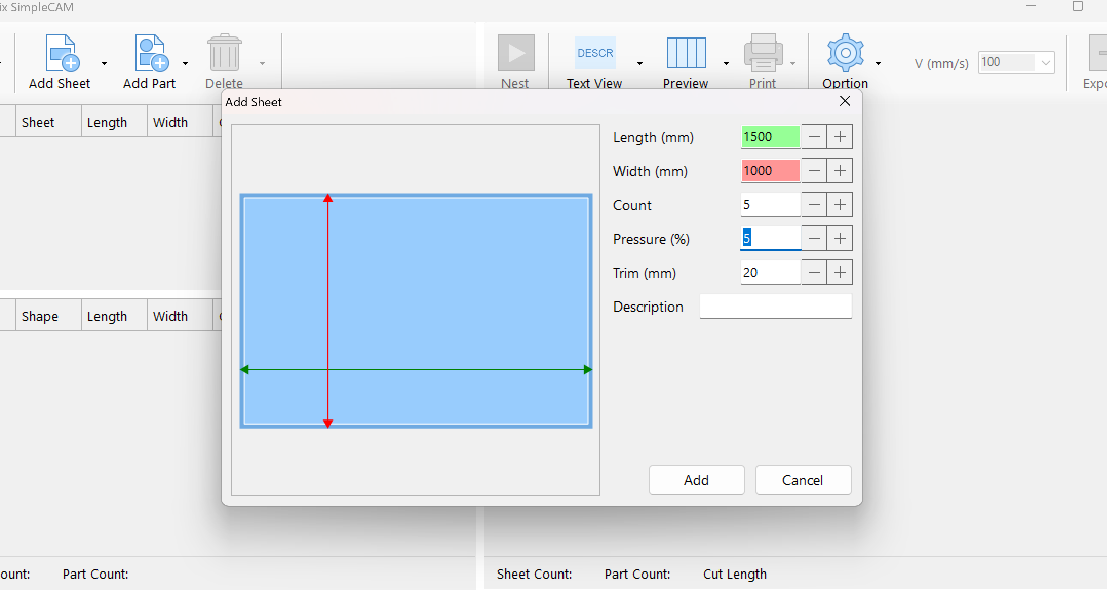
Enhanced Operational Control and Safety with S-CAM’s Pressure Adjustment Feature
S-CAM includes an innovative feature that allows operators to input desired pressure settings directly into the system. This input is then integrated into the machine’s operational parameters, providing a tailored approach to material handling and tool engagement:
- Operator Input for Pressure Settings:
- Operators can directly set the desired pressure levels via the control interface. This input is crucial for adapting the machine’s performance to the specific needs of the material being processed.
- Integration into Sheet Settings:
- Once entered, these pressure values are incorporated into the machine's sheet settings. This integration ensures that the machine applies consistent, optimal pressure throughout the cutting or processing cycle, enhancing both the precision of the operation and the quality of the final product.
- Safety and Convenience:
- By allowing operators to specify pressure settings, S-CAM minimizes the risk of manual errors and material damage. This feature not only makes the operation more convenient but also significantly increases safety, reducing the likelihood of accidents caused by inappropriate pressure levels.
This parameter adjustment capability is especially effective in environments where material specifications vary widely, requiring frequent adjustments to machine settings to ensure optimal handling. The ability to quickly and accurately modify pressure settings according to operator input helps maintain high operational standards and adaptability.
These settings are particularly important in machines equipped with variable pressure capabilities, allowing operators to fine-tune the cutting process based on the thickness or type of glass being processed. By adjusting these values, the CNC controller can dynamically alter the cutting pressure in real-time to optimize the cutting quality and efficiency while safeguarding the integrity of the glass.
One Stage Aligned Enabled
CNC Alignment Using One Stage Align Parameter with a Square and Laser Sensor
Objective:
- To achieve precise alignment of objects on a CNC table by using a combination of a physical square for one side and a laser sensor for the other side.
Process Overview:
- Initial Setup:
- Place the object (e.g., a glass sheet) on the CNC table.
- Align one edge of the object manually with a fixed square or a straight edge fixed to the table. This edge serves as a reliable, consistent reference point.
- Laser Sensor Alignment:
- Use a laser sensor to align the opposite side of the object. The sensor detects the exact position of this side relative to the machine's coordinates.
- Adjust the CNC controls to set the laser alignment based on the detected position. This ensures that the object is perfectly parallel and aligned correctly for precise machining.
- Activation of One Stage Align Parameter:
- Once the manual and laser alignments are set, activate the One Stage Align Parameter. This parameter takes into account the fixed alignment from the square and the precise positioning from the laser sensor.
- This hybrid approach minimizes alignment errors and ensures that the processing of the object is both accurate and efficient.
- Processing Commencement:
-
With the object secured and properly aligned, the CNC machine can begin the cutting or engraving process. The combination of manual and laser-guided alignment ensures that the operation proceeds with the highest level of accuracy.
PedalTo clarify the process of aligning glass sheets on a CNC table using automated or manual methods and adjusting for deviations, here's a structured overview of how different alignment mechanisms function, including the roles of the auto-align feature, corner jacks or fixed squares, and the alignment pedal:
Glass Sheet Alignment Process on CNC TableInitial Setup:
- Sheet Placement: The glass sheet can be placed on the CNC table either automatically or manually. This initial placement may have some deviations.
- Deviation Adjustment: If there's a deviation in the position of the sheet, there are mechanisms in place to adjust and align it correctly before the cutting process begins.
Alignment Modes:
- Fully Automatic by Laser:
- The laser system scans the glass sheet to detect its exact position and orientation.
- Automatically adjusts the position of the glass to align it precisely for cutting.
- Corner Jack or Fixed Square Mode:
- Utilizes a mechanical approach where corner jacks or a fixed square, which can protrude from underneath the table, help in aligning the glass.
- The alignment pedal plays a crucial role in controlling these mechanical aligners.
Alignment Pedal Functions:
- First Press: Activates the corner jack or fixed square. This is the initial step where the mechanical aligner lifts to adjust the sheet’s position against a predetermined point or edge for correct alignment.
- Second Press (with a Definable Time Delay): Turns on the blower. The blower eases the movement of the glass sheet, making it more comfortable for operators to manually adjust the sheet into the proper position.
- Third Press: After the glass reaches the desired position, the third pedal press causes the corner jack to retract, and the blower turns off, securing the glass in place for processing.
Sequence of Operation:
- Activation: Operators initiate the alignment process using the pedal, adjusting based on how many times it is pressed and the functions assigned to each press.
- Adjustment and Finalization: The sequential use of the pedal in conjunction with corner jacks or fixed squares and blower assists in precisely positioning the glass sheet. After alignment, cutting operations can proceed with the glass securely and correctly positioned.
This system ensures high accuracy and ease of operation, reducing the likelihood of errors due to misalignment and enhancing the overall efficiency of glass cutting on CNC tables. The integration of mechanical and automatic alignment features provides flexibility to adapt to different operational needs and glass sheet specifications.
ZAxis DelayImplementation of Time-Based Z-Axis Control in CNC Glass Cutting Machines
In the operation of CNC glass cutting machines, precise control of the Z-axis, which governs the vertical movement of the cutting tool, is crucial. The implementation of a time-based control system for the Z-axis movement was developed to enhance the machine's adaptability to varying glass thicknesses.
The
ZAxisDelayparameter in CNC glass cutting machines is crucial for managing the time it takes for the Z-axis jack to descend and reach the surface of the glass sheet. This parameter is essential for ensuring precision in the cutting process, especially given the delicate nature of glass.Search VelocityLaser Search Velocity in Auto-Aligning**Overview:**In CNC glass cutting operations, particularly during the auto-align phase, the velocity at which the laser searches for alignment points on the glass is critical. This parameter—distinct from
ZAxisDelay—is specifically designed to control the speed of the laser scanning mechanism.Functionality:
- Purpose: The primary purpose of this velocity control parameter is to optimize the laser's speed during the searching phase. This ensures that the laser can efficiently and accurately scan the entire surface or the edges of the glass sheet to determine the optimal starting point for cutting.
Search precisionAdjusting the velocity parameter of the laser during the auto-align process in CNC glass cutting machines is a critical factor for ensuring the accuracy and efficiency of the operation. Let’s explore how this parameter influences the search process and why it is so crucial.
Importance of Laser Search Velocity in Auto-AligningPurpose and Impact:
- Precision Enhancement: The velocity at which the laser moves across the glass surface determines how accurately the edges and key points are detected. A controlled velocity ensures that the laser has sufficient time to register all relevant details of the surface, which is essential for complex or detailed cutting tasks.
- Efficiency Balance: While a slower speed may enhance the detail captured by the laser, it also increases the time required for the scanning process. Therefore, finding an optimal speed that balances detail capture and operational efficiency is key.
Process in Glass InterfacePeelingIn CNC glass cutting applications, a specialized machine interface often includes automated processes to handle various coverings. For example, some glass pieces come with a protective paper layer that must be removed before cutting; CNC machines can integrate an automated removal feature to streamline this step. On the other hand, if the cover is plastic, it's generally left intact since it won’t interfere with the cutting process.
Advanced glass CNC machines, particularly multifunctional models, are designed for efficiency in large-scale or complex jobs. These machines can cut, label, and remove specific coverings (like paper) within a single operational flow, reducing downtime and manual handling. This is especially beneficial in industries where precision and repeatability are critical, such as optical manufacturing and complex component creation
The process of automatic film removal in CNC glass cutting machines involves several integrated systems and technologies that optimize both the efficiency and precision of the operation. Here’s a general overview of how these systems work:
- Integrated Systems: Advanced CNC glass cutting machines combine multiple functions into one process. For instance, some machines are equipped with systems that can automatically detect and remove films from glass surfaces before initiating the cutting process. This integration helps streamline operations and reduce manual intervention, making the process more efficient.
- Mechanical and Motorized Components: Machines often use motorized metal brushes or grinding wheels to perform the film removal. This method is particularly effective for low-emissivity (Low-E) films, which are common in performance glass used in architectural and vehicle applications. The mechanical action of the brush or wheel removes the film without damaging the glass underneath.
- Control Systems: CNC machines are equipped with sophisticated software that controls the operation. This software can adjust parameters such as speed and pressure based on the type of glass and the specific requirements of the film removal. The precision of the control system ensures that the film is removed effectively while maintaining the quality and integrity of the glass.
- Customization and Flexibility: Many of these systems offer customizable settings that allow operators to adjust the machine for different types of glass and film, depending on production needs. This flexibility is crucial for manufacturers who deal with various glass types and coatings.
- Process Integration: Some glass cutting tables are designed to perform not just cutting and film removal but also additional processes like loading and breaking the glass. This multi-functional capability significantly enhances productivity by consolidating multiple manufacturing steps into a single piece of equipment.
The Peeling Process for Coated Glass in Radonix ControllersCoated glass, often protected with a layer that can impede the effectiveness of a diamond cutting tool, requires a specialized approach to ensure precision cutting. Radonix controllers manage this challenge through a systematic peeling process, detailed below:
- Brush Movement:
- Preparation: Once the design is input into the controller, the brush tool is activated to trace the paths where the diamond tool will eventually cut. This step is crucial as it removes the protective coating only along these specific trajectories, thereby preventing any interference during the actual cutting phase.
- Tool and Offset Configuration:
- Tool Placement: Similar to the placement of the laser sensor, both the peeling tool and the diamond are aligned with precise offsets. This setup ensures that each tool operates without colliding or overlapping incorrectly, which is vital for maintaining the integrity of the glass and the accuracy of the cut.
- Offset Consideration: The distance between the peeling tool and the diamond, known as the offset, is critical for the operation. Accurate offset settings ensure that the peeling tool does not extend beyond the required peeling area, preventing unnecessary removal of the protective coating.
- Setting the Peeling Offset:
- Configuration: Each tool in the Radonix system, including the peeling tool, has a distinct offset value which must be accurately configured to align with the diamond tool’s cutting path. These offset values are meticulously calculated and stored under the 'glass' category in the controller's settings, specifically under the 'X' parameter labeled 'Peeling Offset'.
- Precision: The offset values are essential for the precise operation of the peeling tool; they are measured relative to the tip of the diamond and adjusted for both axes to ensure that the peeling accurately exposes the paths needed for cutting without damaging the surrounding areas.
Integrating these meticulous settings into the Radonix controllers enables the machine to efficiently handle glass with protective coatings. By ensuring that the paths for the diamond tool are precisely cleared through the peeling operations, the system guarantees optimal functionality of the cutting process and enhances the quality of the final product.
Auto AlignThe "Auto Align" feature you described is an advanced automation process utilized in CNC glass cutting machines. Here's a refined explanation of how it works, particularly suited for heavy or awkwardly aligned glass sheets:
"In the scenario where a glass sheet is placed on the CNC machine's table and proper alignment is challenging due to its weight or size, the 'Auto Align' feature becomes essential. This function leverages laser sensing technology to automatically detect the physical boundaries and orientation of the glass sheet. Upon initialization, the system first identifies the left edge of the glass, then proceeds to pinpoint two additional reference points along the lower edge. These three points collectively allow the CNC controller to calculate both the reference position and the rotation angle of the glass sheet. Consequently, the design or cutting path is automatically adjusted to match the detected orientation of the glass, ensuring precise execution of the intended design without the need for manual input of alignment points. Unlike processes such as air-gas plasma cutting, which may require manual setting of reference points, this feature streamlines operations by automating adjustments based on the glass sheet's dimensions and orientation, thus enhancing efficiency and reducing setup time.
Laser Sensor SetupWhen setting up CNC machines for glass cutting, particularly when using a laser sensor in conjunction with a diamond cutting tip, it's crucial to accurately calibrate the laser sensor's offset. Here's how you might go about this:
Define the Offset : The offset values for the laser sensor relative to the diamond tip are essential for accurate alignment and cutting. These should be entered into the machine's control system under the specific settings for glass cutting, typically labeled as 'X or Y laser sensor offset relative to the diamond tip'.
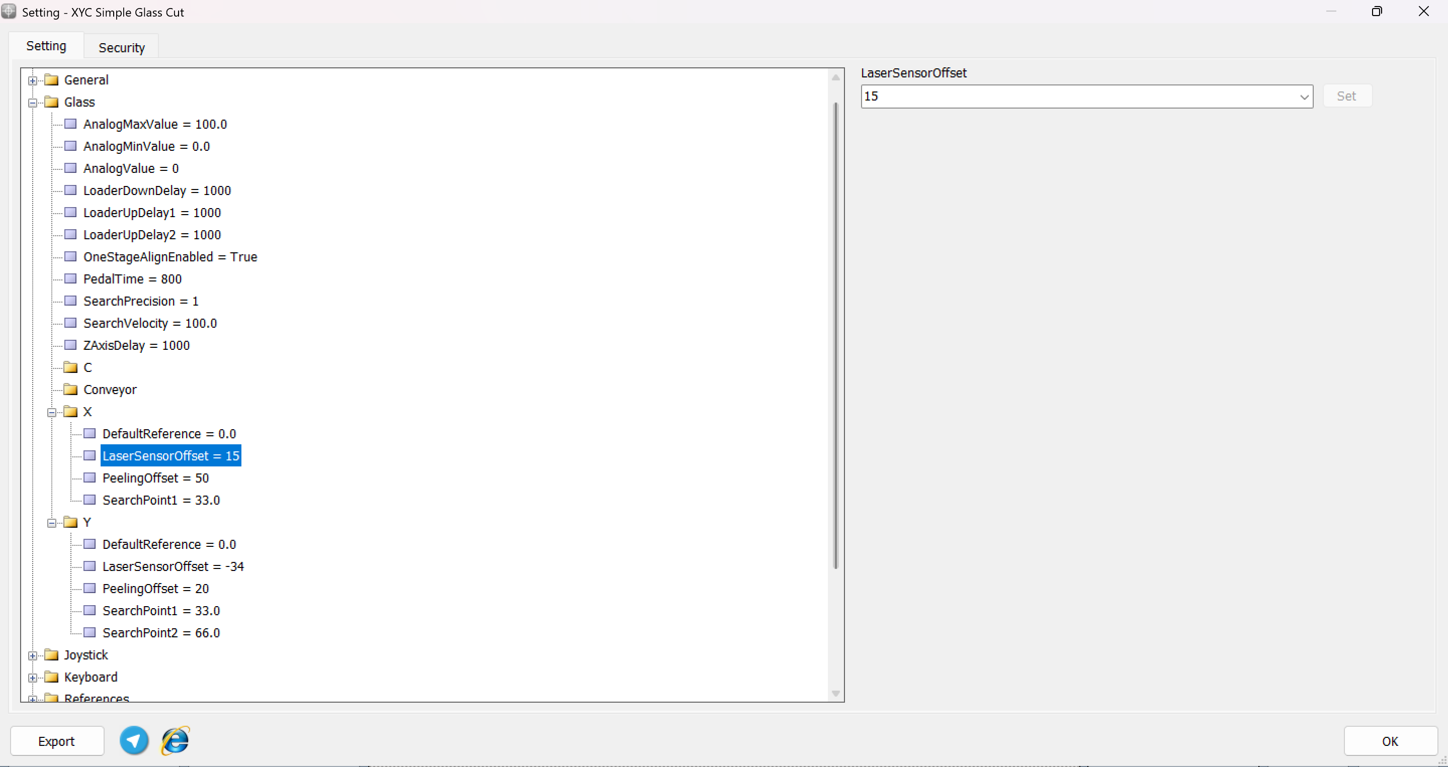
- Zero Reference Point: Consider the position of the diamond tip as the zero reference point. This is the baseline from which the offset of the laser sensor is measured.
- Inputting Values: If the laser sensor is positioned in a way that it extends beyond the diamond tip towards the direction of cutting, this should be inputted as a positive value. Conversely, if it is set back from the diamond tip, the value should be negative.
This setup ensures that the laser sensor accurately detects the edges and surface of the glass sheet, compensating for its physical separation from the diamond tip. This calibration is critical for the precise execution of the design, as it directly affects the alignment and the quality of the cut. Ensuring these settings are meticulously adjusted will lead to better accuracy and reduce the likelihood of errors or material waste during the cutting process.
Search PointTo optimize the laser detection process in CNC machine setups like those facilitated by Radonix controllers, setting the appropriate search points for each axis is crucial. This parameter, which defines the extent of the area the laser will scan to locate the material edges, is adjustable and varies depending on the axis:
- X Axis - Single Value Setting:
- For the X axis, only one value is typically required. This value dictates the search range along the X direction. It's expressed as a percentage of the total available axis length, allowing the system to effectively search within a defined proportion of the axis span.
- Y Axis - Dual Value Setting:
- In contrast, the Y axis requires two values. These define the search ranges at both the starting and ending points of the Y axis, encompassing the full depth of the material to be processed. This dual-point setting is essential for thoroughly scanning the material's vertical span, ensuring that the entire area is accounted for before cutting begins.
These settings are critical for ensuring that the laser positioning system accurately identifies the boundaries of the material, particularly in complex or irregularly shaped items. Adjusting these parameters allows the system to efficiently and effectively prepare for precise cutting operations, reducing the risk of errors and material waste.
Detailed Process for Using the 'Autoalign' Command in Radonix Controllers**Activation of the 'Autoalign' Command:**When the 'Autoalign' command is activated, the device initiates a sequence designed to ensure precise alignment based on the uploaded design specifications.
Setting the Search Point:
- Initialization: The device moves to the width specified in the 'Search Point' parameter, which the user sets based on the design requirements.
- Edge Detection Process: As the device moves, it scans for the edge of the glass. Upon detecting the edge, it returns to its initial position to prepare for a more precise cutting operation.
- Precision Enhancement: The machine then approaches the detected edge again at a reduced speed, allowing for enhanced accuracy in detecting the exact edge position. This step is repeated twice to ensure reliability.
Repetition for Y-Axis for Comprehensive Coverage:
- Y-Axis Scanning: Similar to the X-axis, the device performs the edge detection on the Y-axis. It conducts the scan twice at different points—once at 33% and again at 66% of the axis length—to comprehensively map the edge along the Y-axis.
- Accuracy Confirmation: These repeated scans ensure that the edge detection is accurate and consistent along both axes.
Final Adjustments and Commencement of Cutting:
- Alignment Adjustments: Based on the data collected from the edge detections, the design is finely adjusted to align perfectly with the actual position and orientation of the glass on the machine bed.
- Cutting Initiation: With all parameters set and verified, the device begins the precise cutting process, starting at the confirmed 33% position of the Y-axis.
This process ensures that the Radonix CNC machine accurately aligns and cuts the glass, minimizing errors and maximizing the quality of the final product. The 'Autoalign' feature is crucial for operations that require high precision, particularly in industries where material costs and cutting accuracy are paramount.
FrameThe Frame Process is an essential safety protocol implemented in CNC machining operations to ensure accuracy and alignment before commencing the actual cutting process. This procedure involves maneuvering the cutting tool along a hypothetical perimeter of the design, without material engagement, to verify the correct positioning and operational parameters. By simulating the cutting path, this non-cutting test run helps in identifying any potential setup errors or programming inconsistencies, thereby preventing material waste and tool damage. This preemptive measure is critical in maintaining operational safety and efficiency, safeguarding both the machinery and the workpiece
The Frame Process involves a rapid movement of the tool along the borders of the design, enabling operators to quickly identify the boundaries without any cutting. This swift traversal helps confirm that the setup aligns correctly with the programmed dimensions and design layout, ensuring accuracy before the actual machining process begins.
in fact the Frame Process enables you to define the position of your design within the machining workspace through a demonstration movement. This process moves the tool along the projected boundaries of the design without actual cutting, providing a visual and practical confirmation of the design's placement and alignment on the machine bed. This method is crucial for ensuring that the machining will occur precisely within the intended area, helping to prevent errors and material wastage before the actual cutting begins.
pay attention that this feature just can be achievable after the design has been opened.
S-CAM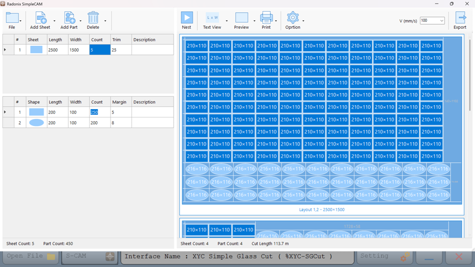
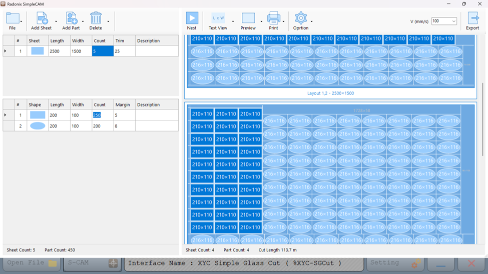
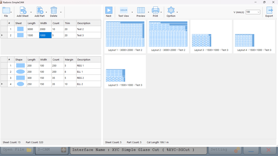 Comprehensive Features of Radonix SimpleCAM
- Seamless Integration and User-Friendly Interface
- Compatibility: Radonix SimpleCAM is specifically designed to integrate seamlessly with Radonix CNC controllers, ensuring flawless operation and communication between software and hardware.
- Intuitive Design: The interface is straightforward, making it easy for operators to quickly learn and master the software, which minimizes training time and facilitates smooth transitions for new users.
- Advanced Nesting Capabilities
- Efficient Material Utilization: Utilizes a sophisticated algorithm to optimize the layout of parts on each sheet, maximizing material usage and reducing waste — crucial for cost-effective glass manufacturing.
- Supports Various Shapes: Accommodates multiple geometric shapes, such as rectangles, ellipses, and polygons, providing the flexibility needed for diverse design requirements.
- Precision and Quality Control
- Trim and Margin Adjustments: These settings allow for precise control over the cutting process, ensuring that each part has adequate space for finishing processes without compromising the dimensions or integrity of the final pieces.
- Speed Adjustments: Operators can control the cutting speed, enhancing the cut quality and extending the lifespan of cutting tools.
- Productivity Enhancements
- Batch Processing and Multitasking: The software can handle multiple sheets of glass simultaneously, allowing for the processing of large orders in less time. This multitasking capability significantly boosts productivity by reducing total production time and increasing throughput.
- Preview and Print Options: Features for previewing the nested layout before actual cutting help verify arrangements and prevent errors. Printing capabilities facilitate easy documentation and communication across the workshop floor.
- Customization and Flexibility
- DXF File Import: Allows operators to import designs directly using DXF files, which is widely used and supports seamless integration with other CAD programs.
- Adjustable Layouts: Manual adjustments to the nesting layout are possible, giving operators the freedom to make last-minute changes based on specific needs or unexpected issues.
- Cost Efficiency
- Reduced Material Waste: By optimizing the use of materials, the software significantly lowers the costs associated with material wastage.
- Efficient Production: Streamlines the entire production process from design to cutting, reducing cycle times and enhancing overall output capacity.
- Dedicated Support and Continuous Updates
- Technical Support: Radonix offers robust customer support and regular software updates to ensure compatibility with the latest technologies and manufacturing practices.
- Run (Green Play Icon): Starts the machining program.
- Pause (Orange Pause Icon): Temporarily pauses the current program.
- Reset (Red Square Icon): Stops the current program and resets it, allowing the operator to start from the beginning if needed.
Relations Between Outputs and Inputsin this part we can investigate the relations between Inputs and Outputs
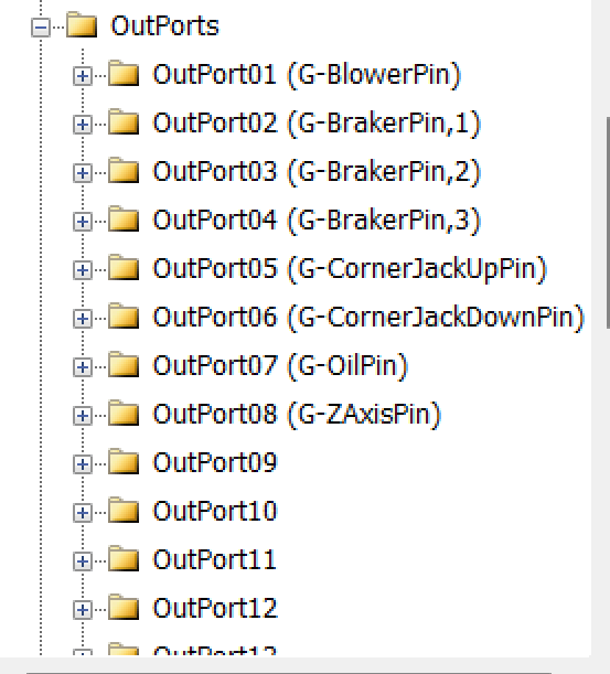
Outputs Lists
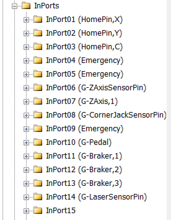
Inputs Lists
InputsIn this section, we will examine the configuration of the Inputs.
Essentially, when the Inports branch is opened, these settings will appear.
Setting Up Inputs: General Overview
Configuring inputs in our CNC system is an essential step to ensure smooth operation, precise control, and safety. Inputs can be categorized into two main types based on their configuration and purpose: Hardware-Based Inputs and Software-Based Inputs. This flexibility allows the system to adapt to a wide range of applications and machine requirements.
1. Hardware-Based InputsHardware inputs involve physical devices connected to the controller, enabling direct interaction with the machine's environment. These inputs are crucial for safety, machine control, and real-time feedback.
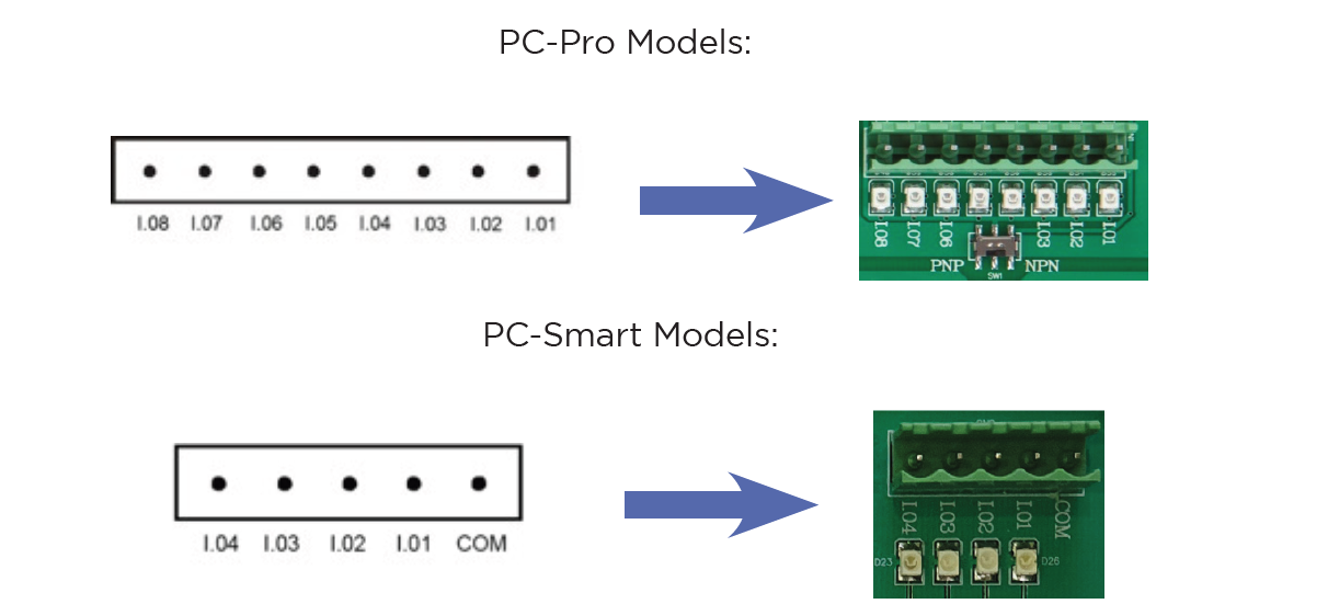
The digital inputs of Radonix controllers are named as I.[n], where n is a number greater than zero and represents the input number. These inputs are isolated by optical couplers and have low noise tolerance due to their low impedance.
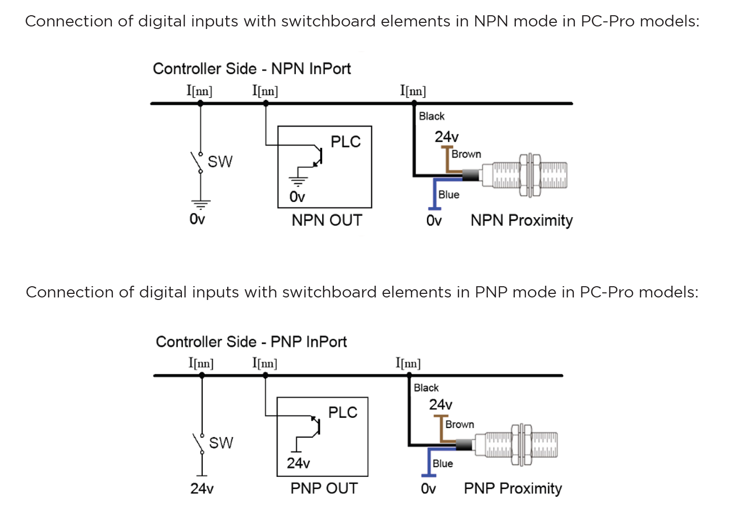
The digital inputs on Radonix controllers have the capability to switch between NPN and PNP modes depending on the output of the device or sensor. The mode changeover switch must be set to PNP position for devices with PNP output and NPN position for devices with NPN output.
In various branches of industrial automation, there are equivalent terms for PNP and NPN. Someexamples of these terms include: NPN = Sink = Low Active PNP = Source = High Active
Switching Between PNP and NPN Modes in Radonix Systems
The ability to switch between PNP (positive logic) and NPN (negative logic) modes in Radonix controllers depends on the specific board model being used. This flexibility allows the system to be compatible with different wiring and sensor configurations.
- PC Pro LAN:
- A small DIP switch is present on the board.
- This switch allows users to toggle between PNP and NPN modes.
- How to Use:
-
Locate the DIP switch on the board.
-
Toggle the switch to the desired mode (PNP or NPN).
-
Ensure the board is powered off before making changes to prevent damage.
-
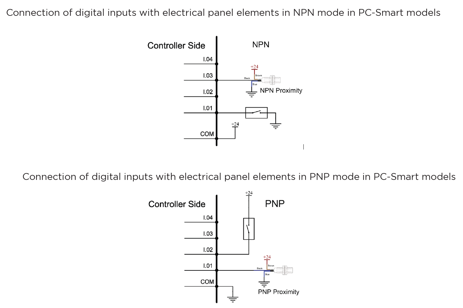
- PC Smart:
-
Instead of a DIP switch, the PC Smart model uses a Come Pin for each set of 4 input pins.
-
This pin allows you to define the input logic (PNP or NPN) for the corresponding inputs.
-
How to Use:
-
Connect the Come Pin to the appropriate voltage (positive for PNP or ground for NPN).
1.PNP Mode (Source Mode):
- If the COM pin is connected to 0V, the input pins will be triggered (turned ON) by a 24V signal.
- In this configuration, the sensor’s output wire must provide a 24V signal to activate the input.
2.NPN Mode (Sink Mode):
- If the COM pin is connected to 24V, the input pins will be triggered (turned ON) by a 0V signal.
- In this configuration, the sensor’s output wire must pull the input to 0V to activate it.
- If the COM pin is connected to 0V, the input pins will be triggered (turned ON) by a 24V signal.
-
Each group of 4 input pins has its own Come Pin, allowing for mixed configurations within the same board.
-
-
Examples of Hardware Inputs:
- Limit Switches: Define physical boundaries for axis movement.
- Home Sensors: Establish the reference (Home) position for the machine most of them are Proximity
- Emergency Stop Buttons: Ensure immediate halting of operations in emergencies.
- Other Proximity Sensors: Detect objects or tools in the machine's workspace.
- Push Buttons and Selector Switches: Trigger specific machine functions or modes.
- Scanners: Measure or detect specific properties, often used in specialized processes such as Glass or gold CNC operations.
Configuration Process:
- Connection: Physically connect the hardware component (e.g., a switch or sensor) to the designated input pin on the controller.
- Input Definition: Use the controller software to define the role of the input (e.g.,
HomePin,LimitPin, or a custom input for specific functions). - Polarity Settings:
- Set the input type as Normally Open (NO) or Normally Closed (NC) based on the connected hardware's default state.
- For example:
- An NC emergency stop button remains active (closed) until pressed.
- An NO proximity sensor activates (closes) only when an object is detected.
2. Software-Based InputsSoftware-Based Inputs provide simple logical functionality to configure arbitrary links and integrate them with related physical hardware .They facilitate quick and simple installation without the need for microprogramming. Users can simply select options from a list and configure settings to maximize efficiency.
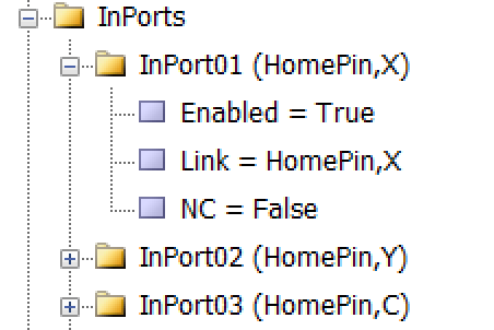
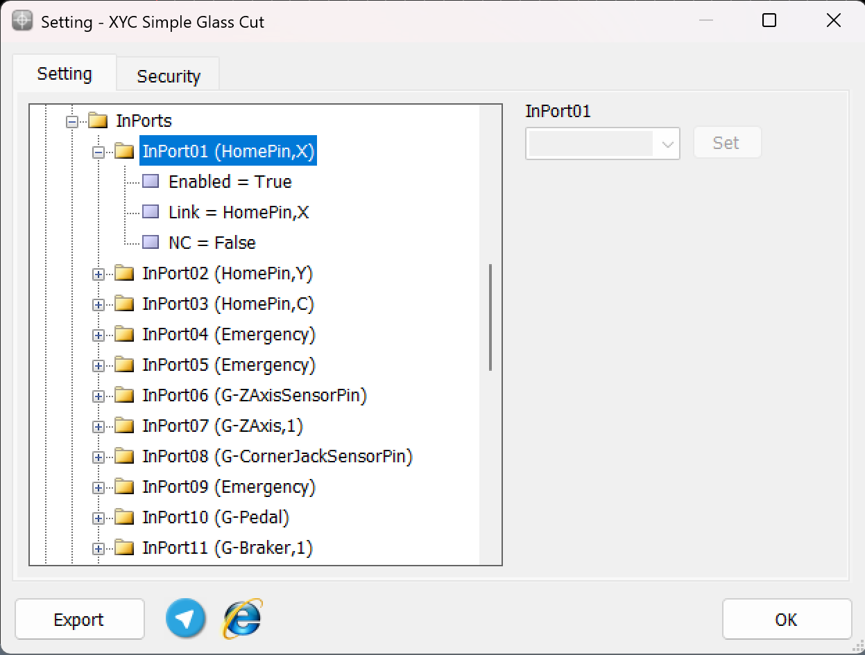
As illustrated in the figure, each input is divided into three sub-branches, as detailed below:
- Enable: This sub-branch can be set to two values: True or False.
- Link: Specifies the duty or task that needs to be performed or checked. This includes any device that can serve as an input, such as sensors, buttons, and switches.
- NC: Determines whether the specific input is Normally Open (NO) or Normally Closed (NC).
Examples of Software Inputs:
- Virtual Limit Switches:
- Use software parameters to define axis movement boundaries based on the machine's table size.
- Logical Triggers: Define conditional triggers for specific operations (e.g., When the axis reaches the limit switch ).
- Simulated Inputs: Use for testing or scenarios where physical components are unavailable.
Configuration Process:
-
Access Configuration Interface:
- Open the controller's software settings to manage inputs.
-
Define Parameters:
As an example to set limit Switch :
-
setting —→ System —→ In ports —→ Enabled= True
Linked = LimitPin,X
NC= True
-
Configure additional logical conditions for interlocks or simulations.
- Validate Settings:
- Test the software by CAM Pro TEST input configurations to ensure proper functionality and safety.
Outputs
In this section, we will examine the configuration of the Outputs.
Setting Up Inputs: General Overview
In Radonix systems, Outports are critical components that manage the output signals controlling various peripherals, such as relays, actuators, alarms, and other devices. Outputs can be categorized into two main types based on their configuration and purpose: Hardware-Based Inputs and **Software-Based outputs.**This flexibility allows the system to adapt to a wide range of applications and machine requirements.
1. Hardware-Based OutputsHardware outputs involve physical signals sent from the controller to external devices, enabling direct control of the machine’s environment. These outputs are critical for operational safety, machine actuation, and real-time command execution, ensuring efficient workflow and coordination within the CNC system.
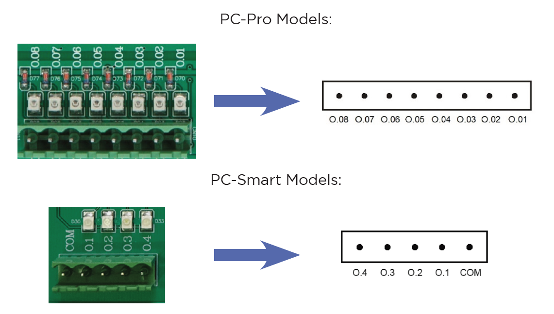
The digital outputs of Radonix controllers are named O."N", where n is a numerical identifier greater than zero and represents the output number .
Radonix controllers incorporate robust protection mechanisms for Outports to ensure durability, safety, and reliability. These mechanisms vary between different models, specifically the PC-Pro and PC-Smart boards, each with distinct protection features and failure handling processes.
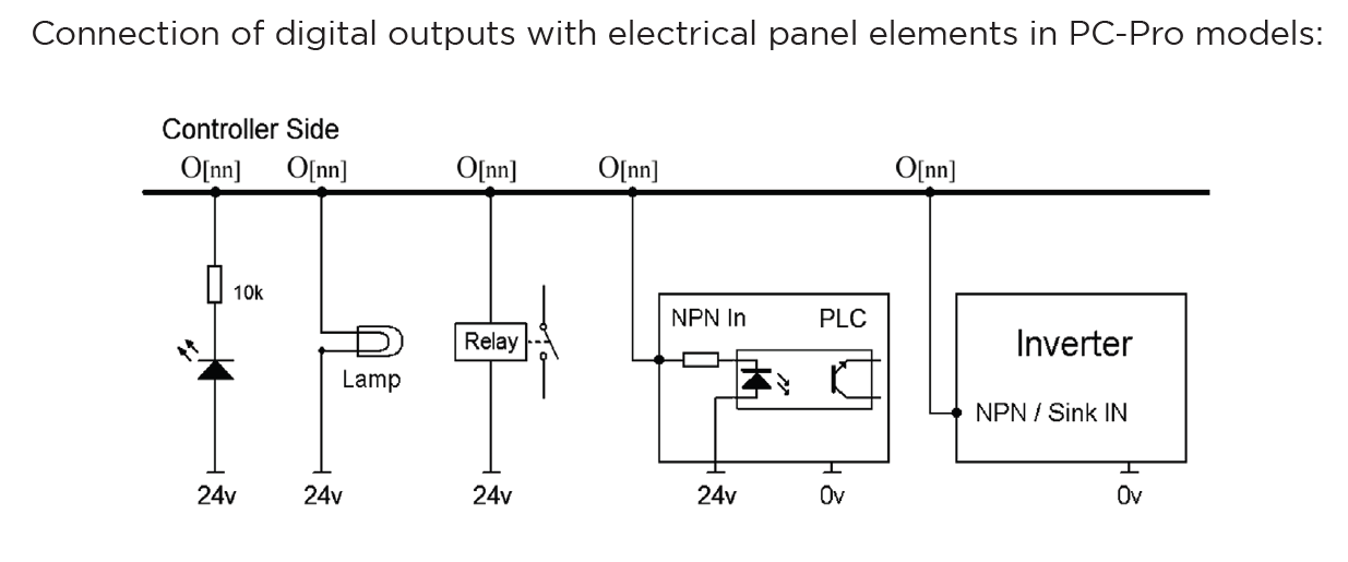
Output Behaviour in PC-Pro LAN Models-
The PC-Pro LAN model outputs are fixed in NPN mode.
-
How It Works:
- When an output is ON, it provides 0 volts by pulling the signal to ground.
- When an output is OFF, it is in a high-impedance state, effectively disconnecting the circuit.
-
Wiring Consideration:
- Connected devices must be compatible with NPN logic, where the load receives voltage from a positive source and is activated when the output pulls the circuit to ground.
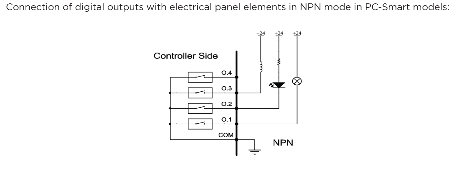
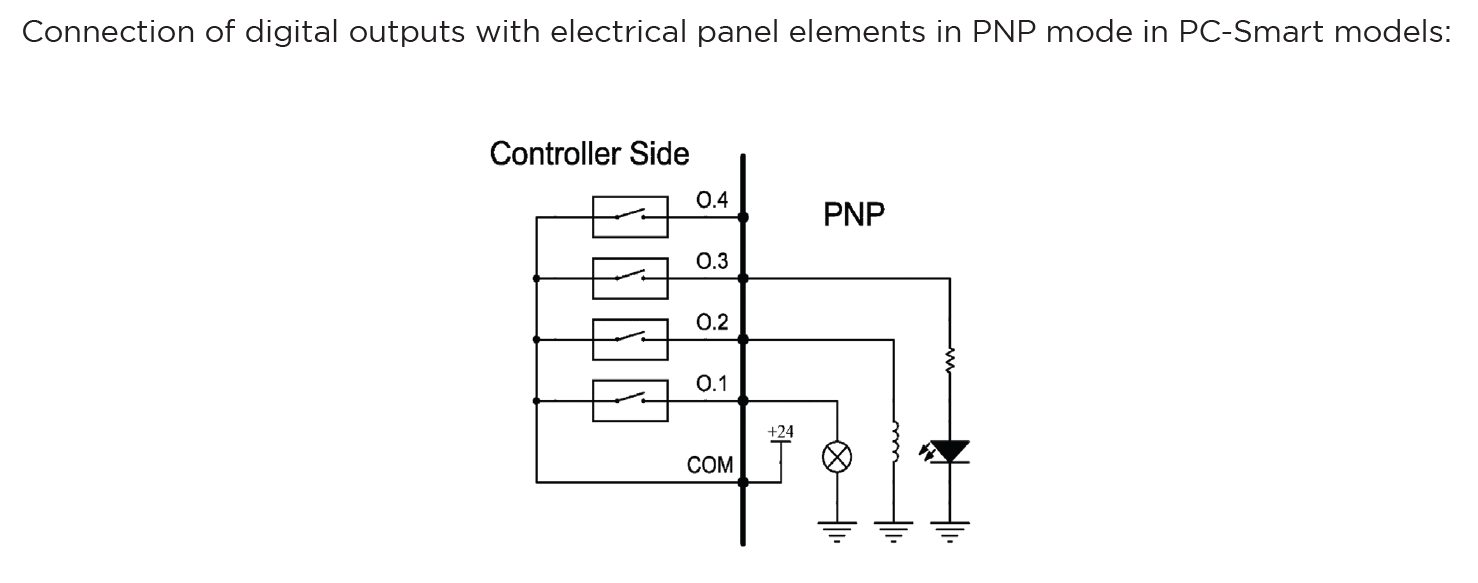
Output Behaviour in PC-Smart Models-
The PC-Smart model offers a flexible configuration where outputs can operate in PNP mode or NPN mode, depending on the connection of the COM Pin.
-
How It Works:
- The voltage provided by the outputs depends on what is connected to the COM Pin:
- COM Pin Connected to 24V: Outputs will provide 24 volts when activated.
- COM Pin Connected to Ground: Outputs will provide 0 volts when activated (NPN mode).
- The voltage provided by the outputs depends on what is connected to the COM Pin:
-
Flexibility:
- This design allows PC-Smart models to adapt to different wiring requirements and device logic preferences.
Configuration Process for Outputs:
- Connection:
- Physically connect the hardware component (e.g., relay, electric valve , Barke , alarm) to the designated output pin on the controller.
- Ensure proper wiring based on the required logic (PNP or NPN) and voltage compatibility.
- Output Definition:
- Use the controller software to define the role of the output (e.g.,
G-BlowerPin,G-BrakerPin,2, or a custom output for specific functions). - Assign the output to its intended device or operation in the system settings.
- Use the controller software to define the role of the output (e.g.,
- Logic Settings:
- Set the output logic based on the connected device's requirements:
- Active High (PNP): The output sends voltage (e.g., 24V) when activated.
- Active Low (NPN): The output pulls the signal to ground (0V) when activated.
- Set the output logic based on the connected device's requirements:
- Testing and Validation:
- After configuring, test the output to ensure it operates as intended in CAM Pro Test application.
- Use a multimeter or other diagnostic tools to verify output voltage and behaviour.
-
2. Software-Based Outputs
Software-Based Outputs provide simple logical functionality to configure and integrate them with related physical hardware. These features are crucial for enhancing control capabilities. They facilitate quick and simple installation without the need for microprogramming. Users can simply select options from a list and configure settings to maximize efficiency.
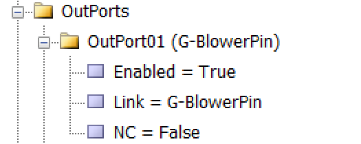
As illustrated in the figure, each output is divided into three sub-branches, as detailed below:
- Enable: This sub-branch can be set to two values: True or False.
- Link: Specifies the duty or task that needs to be performed or checked. This includes any device that can serve as an output, such as actuators, lights, and alarms.
- NC: Determines whether the specific output is Normally Open (NO) or Normally Closed (NC).
Examples of Software Outputs:
- Virtual Relays:
- Use software parameters to define activation boundaries for devices based on operational needs.
- Logical Triggers: Define conditional triggers for activating specific outputs (e.g., alarms or Relay for specific function ).
- Simulated Outputs: Employ these for testing or in scenarios where physical components are not available.
Configuration Process:
- Access the Configuration Interface:
- Navigate to the controller's software settings to manage outputs.
- Define Parameters:
-
To configure an output like an order to forward the VFD, enter parameters.
-
setting —→ System —→ Outports —→ Enabled= True
Linked = C-CutPin
NC= True
-
- Validate Settings:
- Test the configured software outputs to ensure they function correctly and safely, verifying their effectiveness in real-world applications.
Installation and Setup Process for Radonix CNC Controller
Radonix recommends following this detailed step-by-step guide for installing and configuring a Radonix CNC controller. The process encompasses everything from wiring the hardware to setting parameters in the software. This approach aims to guarantee a seamless installation experience for customers, addressing all critical components.
Wiring Components for a Radonix CNC Controller
Proper wiring is the foundation of a reliable and high-performing CNC machine. A professional approach to wiring ensures seamless communication between the Radonix controller, servo or stepper motors, sensors, VFDs (Variable Frequency Drives), and other peripherals. This guide provides expert advice on wiring all components, including selecting appropriate power supplies, ensuring safety, and achieving optimal performance.
1. Main Components Overview
A typical CNC system includes the following components, all of which require precise and secure wiring:
- Radonix CNC Controller: The central control unit.
- Servo or Stepper Motors: Responsible for axis movement.
- Variable Frequency Drive (VFD): Controls the spindle motor.
- Sensors:
- Home Sensors for axis referencing.
- Limit Switches for boundary control.
- Home Sensors for axis referencing.
- Limit Switches for boundary control.
- Emergency Stop (E-Stop): Ensures immediate shutdown during emergencies.
- Power Supplies: Provides regulated power for different components.
- Peripheral Outputs: Includes relays, coolant pumps, and alarms.
2. Wiring the Main Power Supply
Choosing the suitable Power Supply
-
Controller Power Supply:
It is recommended to use 24V switching power supplies to power the Radonix controllers. Calculating Power Supply Current To determine the required power supply current in the electrical panel, the current consumption of each element connected to the power supply must be calculated. For example, if there are 4 relays, 3 pneumatic solenoid valves, and a controller in a switchboard, the current consumption can be determined using Ohm’s law (V=I*R). The electric currents should be calculated and their sum considered as the current of the power supply, along with a confidence factor of a few percent. For example, if the current consumption of the relays is 0.1A and that of the solenoid valves is 0.25A, the total current can be calculated as follows: Total current = controller current + relay current + solenoid valve current IT = 0.5 + 4 * 0.1 + 3 * 0.25 = 1.65A
3. Anti-Noise Measures for CNC Wiring
Electromagnetic interference (EMI) or electrical noise is a common issue in CNC systems, particularly when wiring sensitive components like controllers, servo drives, and sensors. Noise can disrupt signals, cause erratic machine behavior, and even damage components over time. Implementing robust anti-noise measures is critical for ensuring the reliable and precise operation of your CNC machine.
Sources of Electrical Noise
- High-Frequency Devices:
- Variable Frequency Drives (VFDs)- (In Related Machines)
- Switching power supplies
- High-Power Components:
- Spindle motors - (In Related Machines )
- Servo and stepper motors
- Long Cables:
- Longer cables act as antennas, picking up EMI.
- Proximity to Power Lines:
- Signal and power cables running close together can cause interference.
Key Anti-Noise Measures
1. Use Shielded Cables
- Purpose: Shielded cables reduce the effect of electromagnetic interference on sensitive signals.
- Implementation:
- Use twisted-pair shielded cables for signal lines like Pulse+, Pulse-, Direction+, Direction-, and sensor signals.
- Connect the shield to ground at one end only to avoid ground loops.
2. Separate Signal and Power Cables
- Purpose: Prevent high-power cables from inducing noise in low-power signal cables.
- Implementation:
- Route signal cables (e.g., sensor and control signals) separately from power cables (e.g., motor power and VFD output).
- Maintain at least 10-15 cm of separation between these cable types.
- Use different cable trays or conduits for power and signal lines.
3. Proper Grounding
- Purpose: A well-designed grounding system minimizes noise and protects components.
- Implementation:
- Create a central grounding point in the electrical box, often referred to as a grounding bus bar.
- Ensure all grounding wires (controller, drives, motors, etc.) connect to this central point.
- Avoid daisy-chaining ground connections, which can introduce noise.
4. Install Ferrite Beads
- Purpose: Ferrite beads filter out high-frequency noise on signal and power cables.
- Implementation:
- Clip ferrite beads onto signal and control cables near the controller or servo drives.
- Use multiple beads for particularly noisy environments.
5. Proper VFD Wiring
- Purpose: VFDs are a significant source of electrical noise and require special attention.
- Implementation:
- Use shielded cables between the VFD and spindle motor.
- Ground the cable shield at the VFD end.
- Install line filters or chokes on the VFD input and output to suppress noise.
6. Shorten Cable Lengths
- Purpose: Longer cables are more susceptible to picking up noise.
- Implementation:
- Keep cable lengths as short as possible without compromising flexibility.
- Avoid unnecessary slack or loops in the wiring.
7. Use Isolated Power Supplies
- Purpose: Prevent noise from one system affecting another.
- Implementation:
- Use separate, isolated power supplies for sensitive components like sensors, encoders, and the controller.
- Ensure power supplies are adequately rated and properly grounded.
8. Use Optical Isolation
- Purpose: Protect the controller from noise on external connections.
- Implementation:
- Use opto-isolators for connections to external devices like sensors, relays, or switches.
- Many Radonix controllers have built-in optical isolation for inputs and outputs.
9. Secure Connections
- Purpose: Loose connections can act as noise sources.
- Implementation:
- Check all connectors for tight and secure connections.
- Use locking connectors where possible to prevent accidental disconnections.
10. Line Filters and Surge Protectors
- Purpose: Suppress high-frequency noise and protect against voltage spikes.
- Implementation:
- Install EMI line filters on the AC mains supply.
- Use surge protectors on power inputs to the controller and VFD.
Software Configuration: Bringing the System to Life
Step 1: Install Radonix Cam Pro
- Download and install the software on your PC.
- Upon turning on the controller, observe the LEDs on the LAN port: one should remain steady, while the other blinks.
- Connect the Radonix controller to the computer via a LAN or USB cable.
Step 2: Initial Setup
- Open the software and initialize the system.
- Perform a factory reset to ensure default settings are applied.
Step 3: Configure Inputs
- Navigate to Settings > System > Inports.
- Assign roles to each input:
EmergencyStopfor the E-Stop button.HomePin, X/Y/Zfor home sensors.LimitPin, X/-Xfor limit switches.
- Test each input by activating it physically and observing the software response.
Step 4: Configure Outputs
- Navigate to Settings > System > Outports.
- Assign roles to each output:
C-CutPinfor turn on torch.C-ZfreePin,1for active a Relay to move axis Z upward .C-ZfreePin,-1for active a Relay to move axis Z downward .
- Test outputs by toggling them in the software and observing the connected devices.
Step 5: Axis Calibration
- Go to Settings > System > Calibration.
- Enter parameters for each axis:
- Steps per Unit: Based on lead screw pitch, motor steps, and encoder resolution.
- Max Travel: Define the maximum travel distance for each axis.
- Test calibration by commanding movements and measuring actual travel distances.
1. Emergency Stop (E-Stop)
A critical response mechanism in industrial settings used to halt machinery and equipment immediately in order to protect against imminent danger. This action is typically engaged through an emergency stop button or switch that, when activated, interrupts the power supply and ceases all operations, effectively minimizing the risk of accidents, injuries, or damage to the machinery and personnel.
Configurable Emergency Mode
An advanced feature in control systems that allows users to define and set up custom emergency responses through the system settings. This mode can be programmed to engage different levels or types of responses depending on the nature and severity of the threat detected.
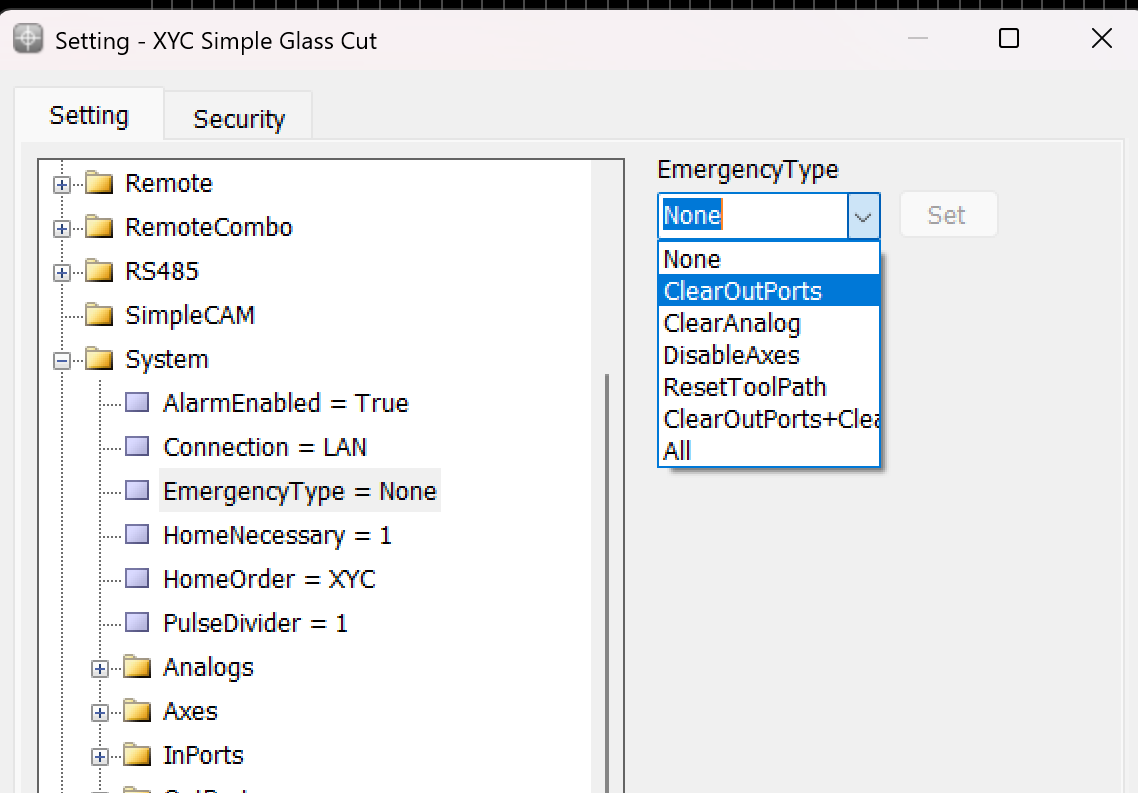
This variable is used to determine the operation that occurs when the Emergency button is pressed.
- None: When this mode is selected, the machine operation is similar to a pause. The device stops all activities but cannot be resumed from the same point if this mode is triggered.
- ClearOutPorts: Activating this mode stops the axes and turns off all digital output ports of the controller. This ensures that no further commands affect the machine's operation until reset.
- ClearAnalog: This mode stops the axes and turns off all analog outputs. It's used to ensure that any variable outputs controlling aspects like tool pressure or spindle speed are deactivated.
- DisableAxes: In this emergency mode, the axes of the machine are stopped and become inactive, which means the motors that drive the axes are disengaged, allowing them to move freely if manually pushed but not under power.
- ResetToolPath: This mode stops the axes and resets the toolpath to the start of the program. This is useful in scenarios where the process needs to be started from the beginning, either to prevent damage or to correct an error.
- ClearOutPorts+ClearAnalog: This comprehensive emergency mode combines the effects of ClearOutPorts and ClearAnalog, stopping all digital and analog outputs, disabling the axes, freeing the motors, and resetting the toolpath to the first coordinate. This is effectively a full reset of the system's operating state.
- All: Selecting "All" activates all the above emergency responses, providing the maximum level of immediate system shutdown. All outputs, both digital and analog, are turned off; axes are stopped and freed; and the toolpath is reset.
2. Home Sensors
Home sensors are so crucial for positions it means that thanks to these sensors the position become meaningful , they are impact in defining table size the sensors are machine zero point or machine origin point when axis reach the sensors the controller detect them and it causes that a red table is created in Black Grid space so with this option each point in this area has its own position than sensors in each axis
Indeed, home sensors are integral to the function and accuracy of CNC machines. Let's explore further how these sensors interact with the CNC controller and influence the machine workspace setup:
Role and Functionality of Home Sensors:
- Defining the Origin: Home sensors establish the machine's zero point or origin. This point serves as the reference for all other positions within the machine's operational space. It ensures that the machine knows the starting point for all axes (typically labeled X, Y, and Z).
- Impact on Table Size and Work Area Definition: The detection of the home position by these sensors directly impacts the definition of the machine’s table size. This is because the machine controller uses the origin point to calculate and define the extents of the machine’s operational area or table. The movements and operations of the machine are confined within these calculated boundaries to ensure precision and to prevent the machine from moving beyond its capable limits, which could cause damage or errors.
- Visualization on Controller Interface: When the home sensors are triggered, the CNC controller can visually depict this on its interface, often illustrated as a "red table" laid out on a "black grid" background. This visual representation helps operators to see and understand the active working area of the machine. It shows where tools can safely travel and operate, providing a clear demarcation of the workspace.
- Positional Accuracy: Each point within this defined red table area has a specific position relative to the machine’s origin point, determined by the home sensors on each axis. This arrangement allows for precise control over the machine's movements and operations, ensuring that every motion made by the machine is accurately accounted for relative to the origin, enhancing both the precision and reliability of the work performed.
- Operational Reliability: Regularly using home sensors to reestablish the machine’s origin point helps maintain operational accuracy and reliability, crucial for long-term consistent output, especially in precision-dependent applications.
Overall, home sensors not only provide a safety mechanism by defining the limits of machine operation but also enhance operational precision by establishing a clear and reliable reference point for all machining tasks. This setup ensures that every point within the operational area is accurately positioned relative to the origin, making the machine's functioning both predictable and precise.
To ensure precise cessation of axis movement after issuing the Home command, the appropriate input links must be configured prior to pressing the Home button, as depicted in the above explanation. This configuration ensures that the machine accurately detects the home position for each axis.
For example:
-
The input HomePin,X is assigned to detect the X-axis home position. This means that when the X-axis sensor aligns in front of its designated home sensor, the system identifies it as the home position.
-
Similarly, other axes such as Y , C , Z require their respective input links, such as HomePin,Y or HomePin,C, to be properly set based on the machine's axes and sensor alignment.
This structured setup allows the machine to halt each axis movement accurately when it reaches its home position, ensuring safe and reliable operation during homing procedures.
3. CalibrationCalibration DefinitionCalibration refers to the process of aligning the motion value of an axis with one of the standard units or with a specific value. Common units in industrial devices are usually millimeters, centimeters, meters, inches, feet, degrees, etc., which are available for use based on the need. Therefore, the concept of calibration for the millimeter unit can be expressed as the alignment of the motion value of the desired axis with the millimeter unit. That is, in the case of measuring with measuring tools, the numerical value of the motion of the axis should be consistent with the measured value in millimeters.***
Motor Types in CalibrationIn Radonix controllers, the calibration procedure for each axis is determined by the motor type. The key requirement for ensuring compatibility with various motor types is that the selected motor must support both pulse and direction signals.
Servo motorsA servo motor is a type of rotary actuator or linear actuator that allows for precise control of angular or linear position, velocity, and acceleration. It typically includes a motor coupled to a sensor for position feedback. Servo motors are essential in applications where precise positioning is required, such as in robotics, CNC machinery, and automated manufacturing. They use feedback signals to adjust motion parameters and can be controlled through servo mechanisms that utilize error-sensing feedback to correct performance.Electronic Gear box:An Electronic Gear Box is an integral component in modern servo systems, especially in applications that involve servo motors, like those used in automation and robotics. This technology essentially functions as a virtual gearbox that adjusts the speed and torque of a motor electronically, rather than mechanically. By manipulating the frequency and amplitude of the motor’s input signals, an electronic gearbox can change the output characteristics of the motor to suit specific tasks without needing physical gear changes.Next step is essential for this subject is : Encoder ResolutionEncoder Resolution is a fundamental specification of servo motors, indicating the number of pulses an encoder emits for each complete revolution of the motor's shaft. This specification, expressed in pulses per revolution (PPR), is crucial for defining the precision with which the motor's position, speed, and acceleration can be controlled.For instance, the Delta servo motor's B2 model features an encoder resolution of 160,000 pulses per revolution. This means that for every full turn of the motor shaft, the encoder generates 160,000 distinct signals. In contrast, the A2 model from the same brand boasts a much higher resolution of 1,280,000 pulses per revolution. This higher resolution allows for even finer control and more precise adjustments, which is essential in applications requiring meticulous positioning and detailed motion control.High-resolution encoders are particularly beneficial in fields like robotics, CNC machinery, and automated assembly lines, where exact movements are paramount. The greater the encoder resolution, the smaller the movement that can be detected and controlled, enhancing the system’s accuracy and the quality of the output. This capability is crucial for optimizing the performance of high-precision tasks, ensuring that each component operates within tight tolerances and adheres to strict quality standards.Understanding and setting the encoder resolution appropriately is a critical first step in the calibration of automated systems. It ensures that the machine operates smoothly and that each part produced meets precise specifications, thereby reducing errors and increasing overall efficiency in manufacturing processes. This detailed control over motor movements is what makes modern automated systems capable of performing complex tasks with high reliability and accuracy.***General Guide to Setting the Electronic Gear Ratio (E.G.) in Servo Drives****OverviewConfiguring the Electronic Gear Ratio (E.G.) for servo drives is crucial for optimizing their performance in applications requiring precise motion control. This guide provides a generic approach to setting E.G. in servo drives, using the Delta B2 servo drive as a specific example to illustrate the process..
Configuring the Electronic Gear Ratio (E.G.) for servo drives is crucial for optimizing their performance in applications requiring precise motion control. This guide provides a generic approach to setting E.G. in servo drives, using the Delta B2 servo drive as a specific example to illustrate the process.
Requirements
- Servo drive with an integrated encoder
- Controller capable of generating pulse signals (e.g., a CNC controller)
- Technical specifications for both servo drive and controller
Step-by-Step Configuration
Step 1: Understand Encoder Resolution
- Objective: Recognize the encoder resolution, which is the number of pulses needed for one complete rotation of the servo motor's shaft.
- General Info: Encoder resolution is specified in pulses per revolution (PPR). It determines the precision with which the servo drive can control the motor position.
Step 2: Calculate Motor Speed in Rounds Per Second
- Objective: Convert the desired motor speed from RPM (revolutions per minute) to RPS (revolutions per second) to match the controller's output frequency.
- Procedure:
- Formula: RPS=RPM/60
- This calculation adjusts the time base from minutes to seconds, facilitating synchronization with pulse output
Step 3: Determine Required Pulses Per Second
- Objective: Calculate the total pulses per second required based on the RPS and encoder resolution.
- Procedure:
- Objective: Calculate the total pulses per second required based on the RPS and encoder resolution.
- Procedure:
-
Multiply the RPS by the encoder resolution to get the required pulses per second.
-
Example Formula: Pulses per Second=RPS × Encoder Resolution
Pulses per Second=RPS ×Encoder Resolution
-
Step 4: Set the Electronic Gear Ratio (E.G.)
-
Objective: Adjust the electronic gearing to enable the controller's output to meet the servo motor's pulse requirements.
-
Procedure:

E.G.=Required Pulses / Controller’s Pulse Capability
- Adjust the controller's settings to match the calculated E.G. ratio.
Example: Delta B2 Servo Drive
- Motor Speed: 3000 RPM
- Encoder Resolution: 160,000 PPR
- Controller's Pulse Capability: 500,000 pulses per second
- Calculation:
- Convert RPM to RPS: 3000 / 60 = 50
-
Required Pulses: 50×160,000 = 8,000,000
8,000,000 pulses per second=50×160,0008,000,000 , \text{pulses per second} = 50 \times 160,000
-
E.G.: E.G.=16=8,000,000 / 500,000
E.G.=16=8,000,000500,000\text{E.G.} = 16 = \frac{8,000,000}{500,000}
- Set E.G. Ratio: 16:1
-
-
Testing and Validation
- Objective: Ensure that the servo system functions correctly under the new settings.
- Procedure:
- Conduct a test run to check the accuracy and responsiveness of the servo drive.
- Observe the motion to confirm that it aligns with expected parameters.
Additional Notes
- Refer to specific servo drive manuals for detailed specifications and advanced settings.
- Regular maintenance checks and recalibration are recommended to sustain optimal performance.
This comprehensive approach ensures that various types of servo drives can be efficiently integrated and operated in systems requiring high precision, such as in automation and robotics.
Stepper motors
A stepper motor is an electromechanical device that converts electrical pulses into discrete mechanical movements. It operates on the principle of electromagnetism, achieving precise movement and positioning by rotating in fixed step increments. This feature makes stepper motors ideal for applications requiring highly accurate and controlled movements such as 3D printers, CNC machines, and robotics. Stepper motors are favoured in systems that require simple, open-loop control for precise short-distance or limited-angle applications.
stepper motor drivers often include DIP (Dual In-line Package) switches that allow users to configure specific settings for motor operation. These switches are critical for adapting the stepper motor's performance to the needs of a particular application. Here's a breakdown of common settings that can be controlled via DIP switches on a stepper motor driver:
Common DIP Switch Settings on Stepper Motor Drivers:
- Microstepping:
- Microstepping is a method of controlling stepper motors so they move in smaller increments. This results in smoother motion and higher resolution positioning. DIP switches allow for setting different microstepping configurations (e.g., full step, half step, quarter step, etc.).
- Current Setting:
- To optimize performance and efficiency, the current output to the stepper motor can be adjusted using DIP switches. This helps match the current to the motor's specifications to prevent underperformance or overheating.
- Decay Mode:
- Decay mode settings control how quickly the motor's current decreases in its off cycle. Proper decay mode settings can improve the performance and response time of the motor, especially at higher speeds or varying loads.
- Torque Settings:
- Some drivers allow the torque output of the motor to be adjusted via DIP switches. This setting is crucial when different loads or pressures are expected on the motor during operation.
How to Use DIP Switches:
- Refer to the Manual: Always check the stepper motor driver’s manual for specific instructions on what each DIP switch controls. This guide is essential for understanding how to correctly set the switches according to your needs.
- Set Before Powering: It’s important to set the DIP switches when the driver is powered off to avoid damaging the motor or the driver.
- Testing and Adjustment: After setting the DIP switches, run tests to ensure that the motor operates as expected under load. Adjust the settings if necessary to achieve the desired performance.
Indeed, setting the DIP switches to the highest microstepping value available on the stepper motor driver is often recommended by experts to achieve the smoothest movement possible. This practice is especially prevalent in applications where precision and smoothness are critical, such as in high-precision machining, robotics, or medical equipment. Here’s a closer look at why this recommendation is prevalent and how to implement it effectively:
Why Set to Highest Microstepping Value?
- Increased Resolution and Smoothness:
- Higher microstepping values increase the number of steps the motor takes to complete one full revolution. This results in smaller step increments, which smooths out the motion, reducing vibrations and resonance that are more noticeable at lower microstepping settings.
- Reduced Mechanical Noise:
- Smaller step increments also contribute to quieter operation. The smoother transition between steps minimizes the noise produced by sudden movements in stepper motors, which is beneficial in noise-sensitive environments.
- Enhanced Positional Accuracy:
- Although microstepping increases resolution, it's important to note that it does not inherently increase the positional accuracy due to potential step errors accumulating over time. However, in practical applications, finer steps allow for more precise control over motor positioning, which can be crucial for delicate operations.
Calibration ways
In Radonix controller, each axis has the ability to calibrate separately, and even the axes can be calibrated in different units. The variable representing the calibration factor in this controller is the Step variable, which to access it, you need to open the Radonix software and after opening the Setting window, go to the System branch and then the Axis"N"sub-branch ("N" represents the number between 1 to 6, which specifies the axis number.
Now based on this E.G calibration process can be feasible through two ways
1. Radonix CAM Calibrator and Measurement
In this calibration method, the basis is measurement with measurement tools and equipment. Therefore, the accuracy of the measuring tool, measurement accuracy, and mechanical errors of the device directly affect the quality of calibration. Although this method is not as precise as computational methods, it is a widely used method due to the lack of information on motors, gearboxes, pulleys, and gear wheels, whichare sometimes not available. The basis of this method is measuring the displacement value for a specific number of pulses. To facilitate, improve accuracy, and speed up calibration using the measurement method, Radonix has provided a free software called CAM-Pro Calibrator, which is automatically installed with the main Radonix software. Based on the physical displacement measurement of the axis and the required number of pulses for this displacement, the software calculates the step value.
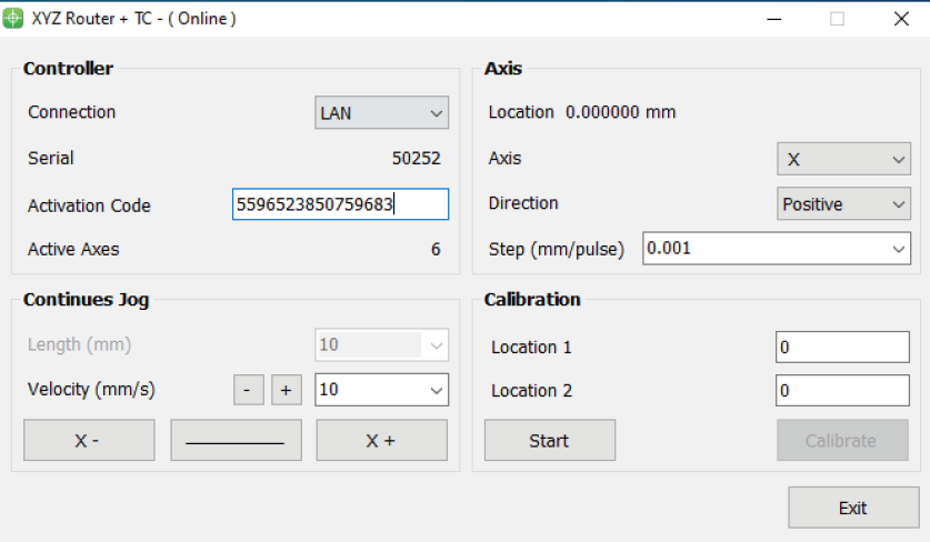
Since pulse counting in this method is the responsibility of the controller, there is no error in pulse measurement. Therefore, the measurement accuracy in this method is directly related to the physical measurement accuracy. In addition, the greater the distance between the two measured points, the larger the pulse value will be, which means the denominator will increase, and according to the constant error, the overall step value obtained will be more accurate. Therefore, calibrating based on two points will result in more accurate results.
Introduction to CAM-Pro CalibratorAs explained in the previous section, the CAM-Pro Calibrator software is installed along with the CAMPro software. There are two ways to find the Calibrator software after installation. According to the first method, simply go to the installation location of the software, which is usually in the C drive of Windows by default, then go to the (x86) Program Files folder, open the Radonix folder, and the CAMProCalibrator software is visible in the Radonix CAM-Pro file. According to the second method, simply go to the Start menu and search for Radonix CAM-Pro Calibrator in the Search option.
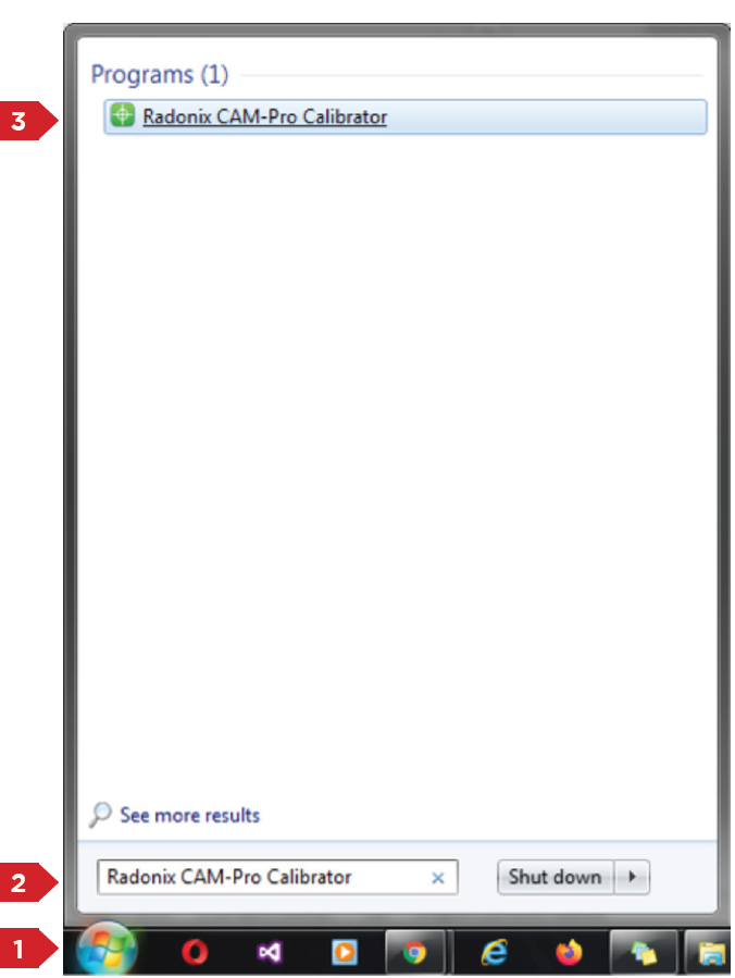
This program consists of two windows. The first window only appears if there are multiple active interfaces on a computer (Figure 3). Through this window, you can select the desired interface and launch it by pressing the 'Ok' button. If there is only one active interface on the computer, the interface selection window will not open, and the main window will open directly.
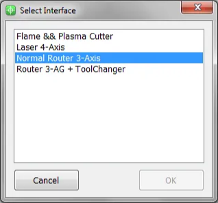
When you open the CAM-Pro Calibrator software, you will see Figure (4), which components are as follows:
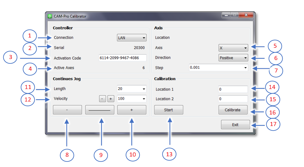
- Connection:
- ProLan controllers must be set to LAN mode.
- ProUSB controllers must be set to USB mode.
- Serial:
- Displays the controller's serial number.
- Activation Code:
- Displays the 16-digit code used to activate axes.
- Active Axes:
- Shows the number of activated axes using the activation code.
Axis Section
5.Axis:
- Allows selecting the desired axis for calibration.
6.Direction:
- Select the appropriate movement direction for standard axes:
- Negative: Movement towards the negative direction.
- Positive: Movement towards the positive direction.
7.Step:
- Sets the step size for calibration or output pulses. After calibration, the step is automatically recorded in the settings.
Continuous Jog Section
8.Negative Jog:
- Enables manual movement in the negative axis direction.
9.Jog Mode:
- Allows selecting the jog movement type:
- Continuous: Smooth, uninterrupted movement.
- Incremental: Moves in defined steps.
10.Positive Jog:
- Enables manual movement in the positive axis direction.
11.Length:
- Defines the incremental movement distance when the Incremental mode is active.
Velocity Section
12.Velocity:
- Used to set the speed for manual movements.
- The positive and negative buttons next to the Velocity option increase or decrease the speed of manual movements.
Calibration Section
13.Start:
- Button to initiate the calibration process.
14.Location 1:
- Used to set the initial position for calibration.
- This position must be relative to a fixed point on the measured axis.
15.Location 2:
- Used to set the final position for calibration.
- This position must also be relative to a fixed point on the measured axis.
16.Calibrate:
- Button to complete the calibration process and calculate the calibration factor.
17.Exit:
- Button to exit the calibration program.
Summary for calibration software, follow these steps:
First, select the desired axis from the Axis section for calibration. Then, by selecting a low speed and moving the axis, ensure the direction of movement is correct. If the movement direction is incorrect, choose the appropriate direction using the Direction section. Next, move the axis to one of the two ends of its travel range. Since the starting direction in this method is not important, it does not matter which end of the axis is chosen as the starting point. Once the axis is in the correct position, measure a point on the axis relative to a fixed point on the machine using an appropriate measuring tool, record this at Location 1, and press the Start button. Note that unit selection is entirely optional, so if calibration with a specific unit is required, all measurements should be based on that unit. For example, the device can be calibrated in units of inches, meters, centimeters, millimeters, or even micrometers.
Move the axis to the opposite end. If measurements at greater distances are possible and the measuring tool is sufficiently accurate, measurements over longer distances will yield more precise results. After moving the axis to the second point, measure this point similar to the first relative to the fixed point on the machine, record this at Location 2, and then press the Calibrate button. Using these measurements, the calibration step or factor is calculated and automatically registered in the designated interface. The calibration process can be repeated as many times as needed for each axis.
Please note that if the activation code has not been entered, an error message will be displayed when opening the CAM-Pro Calibrator software.
2. Mathematics Calculation
Computational MethodTo align the axis movement with the desired unit, a calibration coefficient called "Step" is used. To access this variable, first open the software and then navigate to the Setting window, proceed to the System branch, and the sub-branch Axis"N" (where "N" represents a number between 1 and 6, indicating the axis number). The Step variable is located within these sub-branches, and each axis has its own specific Step variable.
If the unit of axis movement is in millimeters, the unit of this variable will be millimeters per pulse. If the movement unit is centimeters, inches, or any other unit, the Step variable will also be expressed in that unit per pulse. Essentially, this represents the amount of movement of the desired axis per one pulse transmitted to that axis's motor driver. Therefore, to calculate this variable, one must understand the relationship between the motor's movement amount per input pulse to the driver and the conversion ratios of gearboxes, pulleys, and any other type of motion transmission. For a better understanding of these calculations, consider the following examples:
**Example 1:**Consider a linear axis of a CNC machine where the measurement unit is in millimeters, and it is equipped with Panasonic A5 motors that have a 10:1 gearbox ratio. This motor is connected via a pinion with an effective diameter of 66 millimeters to a rack. Now, calculate the Step value for the specified axis.
Please note that each piece of information plays a crucial role in these calculations and can be used to compute the step size of the axis for calibration purposes. For example, knowing the type of motor driver and its specifications determines the relationship between the input pulse to the driver and the resulting movement of the motor shaft.
In Panasonic A5 motors, at a rate of 500,000 pulses per second, the motor reaches a speed of 3000 rpm. In the first step, we calculate the motor's rotational speed per second. Here, the figure 3000 represents the number of motor revolutions per minute, which we convert to seconds by dividing by 60, the number equivalent to one minute. The result is 50, meaning the motor makes 50 rotations per second. Therefore, the equation can be written as: Motor rotational speed per second = 3000 rpm / 60 s = 50 r/s. In the second step, we need to calculate the amount of axis movement per one rotation of the motor.
In fact, in this example, the distance traveled will be equal to the circumference of a circle, and the circumference of a circle is calculated as the diameter of the circle multiplied by π (pi) Or approximately 3.1415 meters. As mentioned in Example 1, a pinion with a diameter of 66 millimeters and a 10:1 gearbox are used in the mechanics, so we will have The amount of axis movement per one revolution of the motor is calculated as (1/10) * 66(mm) * 3.1415 = 20.7339 mm The result obtained is the amount of axis movement per one rotation.
The final step is to write the ultimate equation and find the unknown value, which in this case is the Step variable. As observed, all calculations are based on 500,000 pulses sent by the controller and a motor speed of 3000 rpm. Therefore, to calculate the movement or distance traveled per 1 pulse, the result obtained needs to be divided by 500,000. However, as stated earlier, this motor makes 50 revolutions per second. Thus, it is important to note that while the amount of movement was calculated per 1 revolution in the second step, the motor completes 50 revolutions per second. Therefore, the number obtained in the second step must be multiplied by 50 to find the total distance travelled per second by the motor. Now, we will rewrite the overall equation once more.
Step(mm/pulse) = 50(r/s)∗20.7339(mm) / 500000(pulse/s) = 0.00207339 (pulse/mm)

From this equation, the Step value is calculated. This value means that the motor moves 0.0207339 millimeters per 1 pulse received.
Please note that the computational method used in Example 1 is intended for the calibration of linear axes.
Step(unit/pulse) = The value of the axis movement per one rotation of the motor * the number of motor rotations per second / Number of pulses sent by the controller per second
Example 2: Consider a rotary axis of a CNC machine where the measurement unit is in degrees. It is equipped with Panasonic A5 motors, which have a 25:1 gearbox connected to a 12-tooth pulley. This pulley is then linked via a belt to a 44-tooth pulley. Now, calculate the Step value for the specified axis.
Motor rotational speed per second = 3000 rpm / 60 s = 50 r/s.
In the final step, we must multiply the effective values, such as the gearbox ratio, the pulley ratio, and the motor's rotational speed per second, by 360. As we observed, all calculations are based on 500,000 pulses sent by the controller and a motor speed of 3000 rpm. Therefore, to calculate the movement per 1 pulse, we must divide the obtained value by 500,000. This simple estimation will yield the Step value.
Step= 50(r/s)∗(1/25)∗(12/44)∗360 / 500000(pulse/s) = 0.000392727272
From this equation, the Step value is calculated.
The general equation for calibrating rotary axes is as follows:Step(unit/pulse) = Rotation amount per second in the motor * effective value * 360 * / Number of pulses sent by the controller per second
Please note that whether calculating linear axes or rotary axes, the more significant digits we use, the more precise the calculation results will be.
Please note Pulse divisions in stepper motors directly impact these calculations. For simplicity, one can first calculate the motor rotation for a specific pulse value and then incorporate the result into the equations above.
Please Note In drives where the number of pulses required to reach the maximum motor speed exceeds the number of pulses produced by the controller, one can achieve the maximum motor speed by increasing the electronic drive ratio to a specific extent. For example, if a drive requires 4 million pulses per second to reach the maximum motor speed, and considering that Radonix produces 500,000 pulses per second, an electronic drive ratio of 8 should be considered to achieve the maximum rotational speed of the motor.
4. G-ZAxis
In CNC glass cutting machines, the Z-axis movement is often manually controlled by operators using jacks, distinct from the automatic movements of the X, Y, and C axes which are typically included in G-code programming. This manual control includes specific configurations within the machine's system to ensure precise operation and safety. Here's a breakdown of how this works and the rationale behind using oil in the process:
Manual Control of the Z-Axis
- Input Configuration:
- An input setting is required to initiate movement along the Z-axis. This is usually set in the machine's interface under an 'Inports' branch with a designation like
G-ZAxis,1. - An interface button, linked to this input, is used to control the descent of the Z-axis. This button often functions as a toggle, and accessing the function linked to this button may require a specific key combination (e.g., Ctrl + Shift + Alt + Right Click).
- An input setting is required to initiate movement along the Z-axis. This is usually set in the machine's interface under an 'Inports' branch with a designation like
- Output Connection:
-
The output that activates the Z-axis motor is defined, such as with
G-ZAxisPin. This ensures that when the operator activates the control, the motor engages and the Z-axis moves as commanded. -
Concurrently, oil output is automatically activated to lubricate the movement, preventing damage and ensuring smooth operation.
Importance of Oil in Glass CNC CuttingOil plays a crucial role in the CNC glass cutting process for several reasons:
- Lubrication: It minimizes friction between the cutting tool and the glass, reducing the risk of chipping or cracking.
- Cooling: It dissipates heat generated by the cutting action, protecting both the tool and the glass from overheating.
- Cut Quality: Oil contributes to a cleaner and more precise cut, enhancing the finish and reducing imperfections.
- Tool Protection: By reducing wear on the cutting tool, oil extends its operational lifespan.
- Dust Reduction: Oil helps to bind glass dust created during cutting, which is beneficial for both health and mechanical integrity.
-
Customization and Safety Features
- Customizability: Although the machine comes with a default setup, experts can customize the interface and controls according to specific operational needs and preferences.
- Safety and Sensors: The system includes various inputs for safety features and home sensors. These ensure the machine operates within safe parameters and accurately returns to home positions.
These settings and the use of oil in the CNC glass cutting process highlight the intricate balance of manual control, machine precision, and operational safety, ensuring optimal performance and durability in demanding industrial environments.
5. Braker
In CNC glass cutting machines, specialized equipment is integrated to facilitate the separation of glass sheets. These tools apply controlled pressure beneath the glass sheet to break sections that have been thinned or scored by a diamond cutting tool. The process involves precise pressure distribution, ensuring the glass separates cleanly along the scored lines without causing unwanted cracks or damage to the rest of the sheet. This controlled separation technique is crucial for achieving high precision and maintaining the structural integrity of the glass, especially in applications requiring intricate designs or tight tolerances.
For this purpose, in CNC glass cutting machines, the number of breakers must be considered carefully. Typically, three breakers are installed to handle the separation process effectively. Each breaker requires dedicated input links to receive operational commands and output links to execute those command
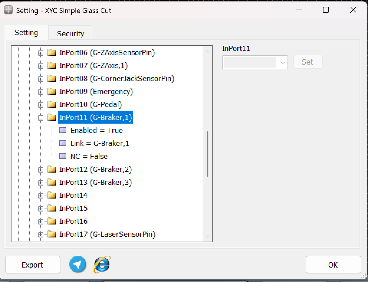
As illustrated in the above description, the appropriate link for this task is G-Braker,n, where n = 1, 2, 3, corresponding to each breaker. These input links are designed to be connected to press buttons located on the control box for manual operation. Alternatively, they can be assigned to other devices such as a remote control, Handwheel, or even a keyboard for more flexible and advanced control options.
This configuration allows operators to issue commands to the breakers conveniently, ensuring smooth integration and adaptability to different operational scenarios. The flexibility of linking these inputs to multiple devices enhances user convenience and operational efficiency in CNC glass cutting machines.
On the other side, the outputs for controlling the breakers must be configured using the format G-BrakerPin,n, where "N" represents the specific breaker (1, 2, or 3). This configuration ensures that each breaker receives its respective command for execution.
For example:
- G-BrakerPin,1: Controls the first breaker.
- G-BrakerPin,2: Controls the second breaker.
- G-BrakerPin,3: Controls the third breaker.
By assigning these outputs properly, the system can manage each breaker individually, allowing for precise and efficient execution of the glass separation process. This structured approach is critical for maintaining synchronization and achieving high-quality results in CNC glass cutting operations.
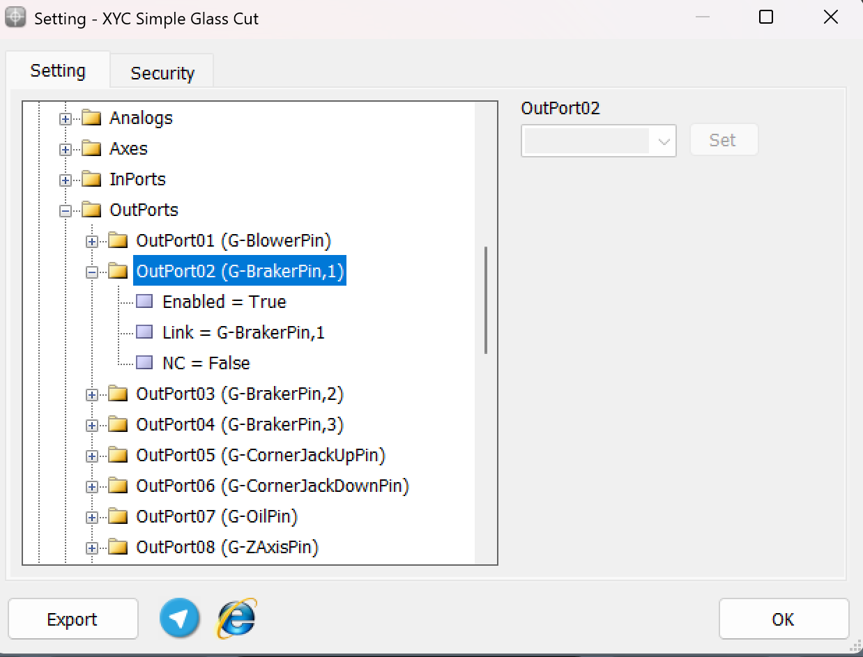
6. Oil
Importance of Oil in Glass CNC Cutting
Oil plays a crucial role in the CNC glass cutting process for several reasons:
- Lubrication: It minimizes friction between the cutting tool and the glass, reducing the risk of chipping or cracking.
- Cooling: It dissipates heat generated by the cutting action, protecting both the tool and the glass from overheating.
- Cut Quality: Oil contributes to a cleaner and more precise cut, enhancing the finish and reducing imperfections.
- Tool Protection: By reducing wear on the cutting tool, oil extends its operational lifespan.
- Dust Reduction: Oil helps to bind glass dust created during cutting, which is beneficial for both health and mechanical integrity.
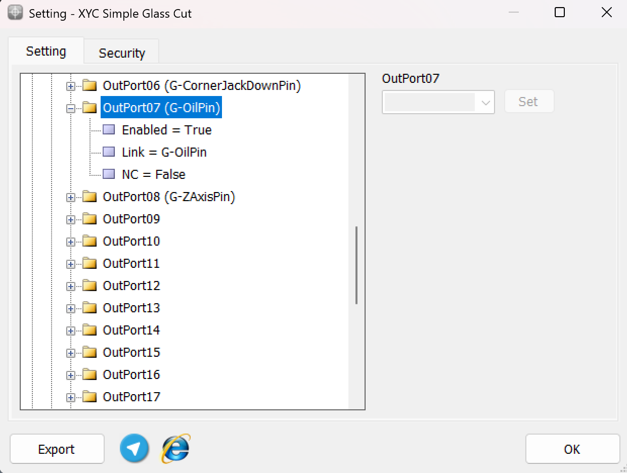
The output for oil control must be configured in the output links using the format G-OilPin. This ensures that the system can activate or deactivate the oil output as required for the operation.
By setting the G-OilPin in the outputs:
- The machine can precisely control the oil flow for lubrication or other tasks during the CNC operation.
- The configuration allows seamless integration with the overall control system, ensuring that oil activation is executed efficiently when triggered by specific commands or processes.
Proper assignment of the G-OilPin ensures smooth functionality and enhances the reliability of the machine's operations.
7. Jack Corner Pin
The squaring tool is an essential component in CNC glass cutting machines, designed to align and position the glass sheet accurately on the machine's table. This tool ensures precision in cutting and helps the operator position the glass at the correct angle and location for cutting operations.
Applications of the Squaring Tool in CNC Glass Machines
-
Glass Alignment:
The squaring tool serves as a reference point to align the glass sheet. Proper alignment ensures precise and clean cuts.
-
Stabilizing the Glass:
Alongside other holding tools like vacuum clamps or jacks, the squaring tool helps to stabilize the glass sheet during cutting, preventing unwanted movement.
-
Manual and Automatic Use:
The squaring tool can be operated manually by the operator or automatically through adjustable jacks that rise from beneath the table to position the glass accurately.
-
Software Integration:
In advanced CNC machines, the position of the squaring tool is integrated into the machine's software. This enables features like Auto Align or Manual Align to adjust the cutting path precisely based on the squaring tool's position.
Advantages
- Enhances cutting precision.
- Reduces errors caused by misaligned glass sheets.
- Simplifies the alignment process for the operator.
- Improves the quality of the final cut pieces.
G-CornerjacksensorpinThe input is for the sensor of the square jack on the table. When this input is activated, it determines whether the angle jack is on or off.
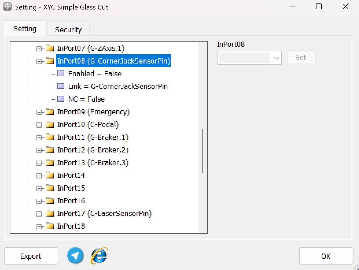
Outputs to Control Jacks in CNC Glass Machines
The outputs used to control the jacks in CNC glass machines are critical for managing operations like lifting or stabilizing the glass sheet during processing. These outputs are defined in the software to send commands to the respective jack motors or actuators.
Typical Output Configuration
-
Output Definition:
- Each jack is assigned a specific output link to control its movement.
- For instance, the outputs are typically labeled as:
-
G-CornerJackUpPin: Controls the upward movement of the jack .
-
G-CornerJackDownPin: Controls the downward movement of the jack.
-
- Functionality:
- Upward Movement: Activates the respective output to raise the jack.
- Downward Movement: Activates the respective output to lower the jack.
- Connection and Control:
- These outputs are connected to the control board's output terminals, which in turn are wired to the jack motors or solenoids.
- Operators can issue commands via the machine's interface or control software to activate these outputs.
Use Cases- Glass Loading/Unloading: Jacks lift or lower the glass sheet during loading and unloading processes.
- Alignment: Jacks help in positioning the glass correctly by adjusting its height.
- Stabilization: They hold the glass securely in place during cutting or other operations.
Configuration in the Software:- Navigate to the System > Outports section.
- Assign output links to each jack :
- G-JackUpPin
- G-JackDownPin
- Assign output links to each jack :
- Set the Enable parameter to True to activate the output.
Proper configuration and usage of these outputs ensure precise control over the jacks, improving the efficiency and accuracy of operations in CNC glass machines.
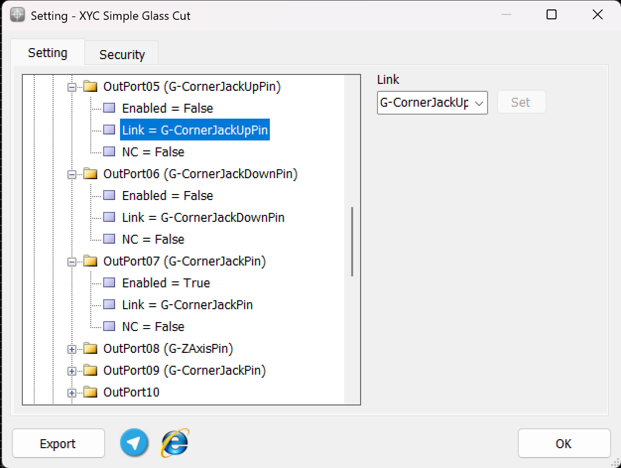
Pedal-Controlled Multi-Task Routine in CNC Glass Machines
In CNC glass machines, a pedal control system is often used to streamline and manage multiple tasks through a single switch. This setup allows operators to perform various operations efficiently by pressing the pedal in a specific sequence. Each press triggers a distinct process, enabling smooth and coordinated operations.
Routine Process
-
First Pedal Press:
- Activates the corner jack, causing it to rise.
- This step positions the glass sheet for alignment or stabilization.
-
Second Pedal Press:
-
Turns on the blower system.
-
The blower creates an air cushion under the glass sheet, making it easier to reposition the glass for alignment.
- Third Pedal Press:
- Deactivates the blower system, turning it off.
- This ensures the glass remains stable and ready for the next stage of operation.
Advantages of the Pedal-Controlled System:-
Simplified Operation: Reduces the need for multiple switches and manual adjustments.
-
Enhanced Workflow: Allows operators to manage tasks quickly and efficiently without leaving their position.
-
Flexibility: The pedal’s multi-functional role adapts to various operational requirements.
-
Configuration and Customization
The pedal system can be customized in the controller software:
- Each press of the pedal is assigned to specific outputs:
- First press: Linked to the jack corner output (G-JackUpPin).
- Second press: Linked to the blower activation output (G-BlowerOnPin).
- Third press: Linked to the corner jack down output (G-JackDownPin)
- Timing and sequence can also be adjusted to meet the specific needs of the operator.