Function of Pins Related to Axes
+VCC
This pin is the voltage output pin from the control card. It can supply up to 100 mA of current for COM+ power.
Direction+ & Direction-
These two pins determine the motor’s direction of rotation. The connection type is line drive, capable of supplying up to 25 mA, and can control two motors in parallel at the same time.
Pulse+ & Pulse-
These two pins determine the motor’s movement amount and speed as digital pulses via a line drive output. They can supply up to 25 mA and can control two motors simultaneously. The electronic circuit diagram for the Pulse and Direction pins is shown in Figure 20.
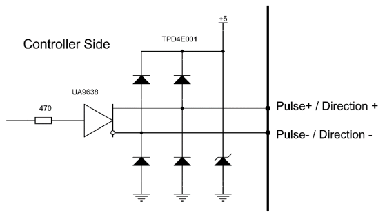
Figure 20 – Internal Circuit of Pulse and Direction Pins
Servo On
This pin is the output pin used to enable the servo motor when the control card becomes active. When active, the SON LED next to each axis connector lights up. The internal circuit diagram of the Servo On pin is shown in Figure 21.
The Servo On pin is not used with stepper motors.
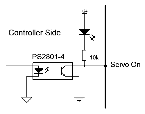
Figure 21 – Internal Circuit of Servo On Pin
Servo Ready
This pin is an input pin isolated by a photo coupler that monitors the servo motor’s status. If a fault occurs in the servo motor’s power, cable breakage, or encoder, this pin reports the status to the control card and the axis motion is halted. In this case, an axis error is displayed in the interface (Figure 22).
The Servo Ready pin is not used with stepper motors.
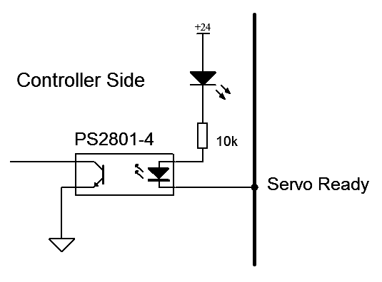
Figure 22 – Internal Circuit of Servo Ready Pin
Encoder Zero
This pin is an input pin isolated by a photo coupler, available only on PC-Smart models, which signals the zero position of the servo motor’s encoder as a pulse to the control card. This pin is used on some devices to find the Home position (Figure 23).
The Encoder Zero pin is not used with stepper motors.
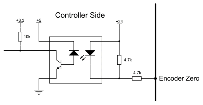
Figure 23 – Internal Circuit of Encoder Zero Pin
Alarm Reset
This pin is an output used to clear faults in the servo drive. If the servo drive reports an error and the error is cleared, the fault can be reset via this pin without powering down the electrical panel, and the servo motor returns to normal operation (Figure 24).
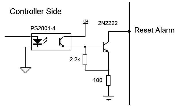
Figure 24 – Internal Circuit of Alarm Reset Pin
GND
The six pins of the axis connector are connected to the control card’s GND, and these pins are used for driver connection.
Direction and Pulse output pins are digital; therefore, avoid connecting these pins to other pins, especially Pin 1.ℹ️
- Reset and Servo On output pins are open-collector, NPN type. When active, they switch GND to the pins. Therefore, drivers connected to Reset and Servo On must be NPN type.
- Ready and Encoder Zero input pins are also NPN type. Thus, servo drives connected to these pins must switch GND to them, i.e., be NPN type.
- When connecting the control card to stepper motors, only the Direction-, Direction+, Pulse-, and Pulse+ pins are used; other pins are not required. However, to allow the control card to detect a cable break as a fault, you can connect Pin 6 and Pin 7 on the DB15 connector. In this case, removing the connector will cause an axis error.
- For user convenience, the wiring diagram between Radonix control cards and various servo motors is provided in Appendix 1.