Calibration Methods
Calibration Methods in the Radonix Controller
Due to existing measurement errors and the need for specific environmental conditions, the calculation method is superior to the measurement method in terms of accuracy for proper calibration. However, to apply this method, one must have knowledge of the power transmission components in the system—such as the motor, gearbox, gears, and, if used, ball screw. Because of the diversity in mechanical structures and the different components used during calibration, attention to these parts is essential for correctly calculating the Step variable. Otherwise, calibration cannot be performed accurately. CNC machine manufacturers should use the calculation method if they have this information, to benefit from high accuracy and avoid concerns related to measurement error.
The calibration methods are:
- Calculation Method
- Measurement Method
Calculation Method
To align the movement of an axis with a specific unit, the Step calibration coefficient is used. To access this variable, open the software and then go to the Setting window, then navigate to the System section and the Axis{n} subsection ({n} represents the axis number, between 1 and 6). The Step variable is located in these subsections, and each axis has its own Step variable.
When the axis movement unit is millimeters, the unit of this variable is pulses per millimeter. If centimeters, inches, or other units are used, the Step variable will be in pulses per that unit. It essentially shows how much movement is achieved for each pulse sent to the motor. To compute this variable, you need to understand the relationship between the pulses sent to the motor driver and the motor's movement, along with the ratios of components like gearboxes, pulleys, and other transmission elements. See the examples below for clarity:
Example 1:
Let’s consider a linear axis of a CNC machine. The measurement unit is millimeters and Panasonic A5 motors are used. These motors have a 10:1 gearbox and a pinion with a 66 mm effective diameter. Let’s calculate the Step value.
Note
Each of these specifications plays a crucial role in the calculation. For example, knowing the type of motor driver helps determine the relationship between the pulses sent and the motor shaft's movement.
In Panasonic A5 motors, when 500,000 pulses per second are sent, the motor reaches a speed of 3000 rpm. First, calculate the motor’s rotational speed per second. Since 3000 rpm means 3000 revolutions per minute, divide by 60 to get revolutions per second:
Motor revolutions per second = 3000 (rpm) / 60 = 50 (r/s)
Second, calculate how much distance the axis moves for one motor revolution. The distance covered will be the circumference of the circle, which is calculated by multiplying the diameter by π (3.1415). According to the given specs (66 mm diameter and 10:1 gearbox):
Axis movement per revolution = (1/10) × 66(mm) × 3.1415 = 20.7339 mm
This gives the movement per one motor revolution.
Now, use this in the final equation. All calculations are based on 500,000 pulses per second and 3000 rpm (50 revolutions/sec). So we multiply the axis movement per revolution by 50, and divide the result by 500,000 pulses:

From this equation, the Step value is calculated. This means the axis moves 0.00207339 mm per pulse.
Note
This calculation method is intended for linear axis calibration.
Note
General Calibration Equation for Linear Axes:Step (unit/pulse) = (Axis movement × Motor revolutions/sec) / (Number of pulses sent by controller)
Example 2:
Now consider a rotary axis of a CNC machine. The measurement unit is degrees, and again Panasonic A5 motors are used. These motors have a 25:1 gearbox, and a 12-tooth pulley connected via a belt to a 44-tooth pulley. Let’s calculate the Step value.
Remember, one shaft revolution = 360 degrees.
Again, with 500,000 pulses per second, the motor reaches 3000 rpm. Calculate motor revolutions per second:
Motor revolutions per second = 3000 / 60 = 50 (r/s)
Now, multiply the gearbox ratio, pulley ratios, and motor revolutions per second by 360° to determine the total movement. Divide the resulting value by 500,000 pulses to get the movement per pulse. This gives us the Step value:
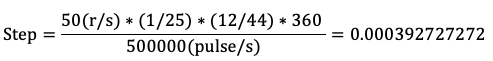
This equation provides the Step value.
General Calibration Equation for Rotary Axes
Step (unit/pulse) = (Motor revolutions/sec × Effective Ratios × 360°) / (Pulses sent by controller)
Notes
- For both linear and rotary axis calculations, using more significant digits leads to more accurate results.
- Pulse divisions in stepper motors directly affect these calculations. First calculate how much the motor rotates for a specific pulse count, then insert that result into the equations above.
- If the number of pulses required to reach the motor’s maximum speed exceeds the controller’s output capacity, increase the driver’s electronic multiplier ratio. For instance, if a motor requires 4 million pulses per second to reach its max speed, but Radonix outputs only 500,000 pulses/sec, the electronic multiplier on the driver should be set to 8.
Updated about 1 year ago