Marble and Stone (Landscape)
Radonix Landscape – Intelligent Layout Software for Stone CNC Machining
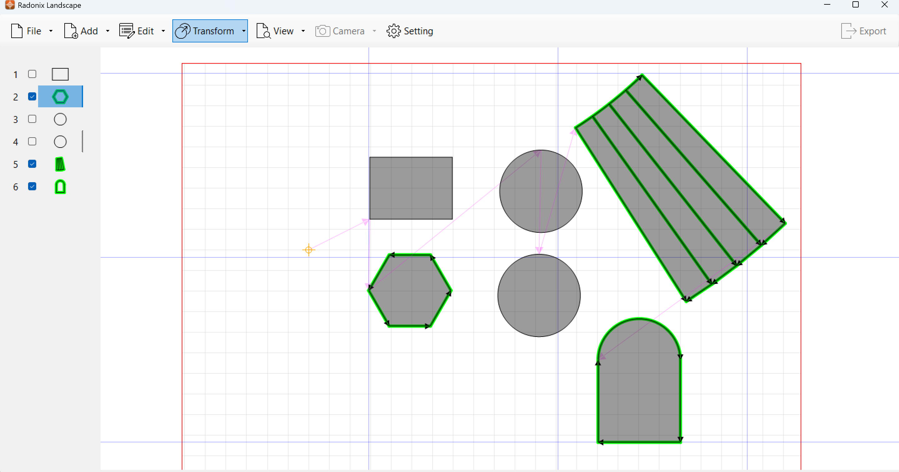
Radonix Landscape is a powerful software solution tailored for marble and stone CNC machines, designed to streamline the layout and cutting process. With its intuitive interface and advanced features, this software enables users to precisely position designs on stone sheets, ensuring optimal material usage and accurate machining.
Key Features
- Integrated Camera Support: Capture and import high-resolution images of stone sheets, allowing users to align designs on a 1:1 scale.
- Comprehensive Shape Tools: Easily add lines, rectangles, ellipses, polygons, and grids to create custom designs. The software also includes advanced shapes like arcs and stair structures, making it ideal for architectural stone applications.
- DXF Import Support: Users can import DXF files for seamless CAD integration.
- Flexible Design Placement: Drag, rotate, and arrange shapes manually for precise positioning on the material.
- Grid-Based Alignment: A structured grid system enhances accuracy, making design positioning easier and more controlled.
- Machine-Specific Settings: Configure cutting parameters such as rotation angles, saw diameter, offsets, and tool dimensions for optimal CNC performance.
- Efficient Workflow Tools: Features like file import/export, shape transformation, and path visualization optimize the preparation process before CNC cutting.
- Path Visualization and Adjustment – Users can manually adjust processing paths to optimize material usage and reduce cutting time.
- Set Reference for Precise Positioning – Users can define a new reference point, ensuring accurate alignment of designs on the material before processing.
With Radonix Landscape, CNC operators can maximize material efficiency, reduce errors, and enhance productivity in stone cutting and engraving applications.
Settings User Manual
1. Overview of Settings Form
The Settings Form in Radonix Landscape allows users to configure essential parameters for camera setup, object movement, grid alignment, machine control, reference positioning, and table dimensions. Adjusting these settings ensures precise design placement and efficient CNC machining.
The Settings Form consists of two main sections:
- General Settings – Controls for camera, movement, grid options, machine parameters, reference points, and table dimensions.
- Display Settings – Adjustments for visual presentation and user interface preferences.
2. Camera Settings
Radonix Landscape integrates a camera system for capturing material images. The following options allow users to optimize camera performance:
- Camera Brightness (%) – Adjusts the brightness of the captured image for better visibility.
- Camera Enabled (True/False) – Enables or disables the camera functionality.
- Camera X1 (mm), X2 (mm), Y1 (mm), Y2 (mm) – Defines the coordinate range of the camera’s working area, ensuring accurate image alignment with the machine’s workspace.
Best Practices
- Set Camera Brightness to a suitable level for clear image visibility.
- Adjust camera coordinate limits to match the actual machine workspace.
- Ensure the Camera Enabled option is turned on when capturing material images.
3. Edit Settings
These settings define movement and rotation steps for object manipulation within the software:
- Move Step (mm) – Controls the distance an object moves when using directional controls.
- Rotation Step (°) – Sets the rotation increment when rotating objects.
Best Practices
- Use smaller step values for fine-tuning object placement.
- Increase step size for faster object adjustments when working on large designs.
4. Gridline Settings
The grid system helps users align designs accurately within the workspace.
- Gridline Step (mm) – Defines the spacing between grid lines.
- Show Gridline (True/False) – Enables or disables the grid display.
Best Practices
- Keep the grid enabled for easy reference while positioning objects.
- Adjust grid spacing based on material size and CNC precision requirements.
5. Machine Settings
The Machine Settings section allows users to configure CNC machine parameters for precise cutting and machining control.
- A Max Course (°) – Defines the maximum rotation angle for the A-axis.
- C Max Course (°) – Specifies the maximum rotation angle for the C-axis.
- C Min Course (°) – Defines the minimum rotation angle for the C-axis.
- Machine Type – Identifies the machine configuration (e.g., Router_XYZCA) to ensure compatibility with the CNC system.
- Rotation Threshold (°) – Sets the tolerance level for rotation, ensuring smoother adjustments during machining.
- Saw Diameter (mm) – Configures the diameter of the cutting tool, crucial for defining cutting paths.
- Saw Thickness (mm) – Determines the thickness of the saw blade, affecting material removal and precision.
- Z Slow (mm) – Adjusts the Z-axis movement speed, controlling vertical positioning for precise depth adjustments.
Best Practices
- Set rotation limits based on machine capabilities to avoid excessive motion errors.
- Ensure machine type selection matches the actual hardware configuration.
- Adjust saw parameters correctly to ensure proper cutting depth and material integrity.
6. Offset Settings
The offset settings define the mechanical offsets that impact tool positioning:
- X Offset (mm) – Adjusts the tool’s horizontal position.
- Y Offset (mm) – Defines the tool’s vertical offset.
- Z Offset (mm) – Controls the depth offset, affecting how deep the tool moves into the material.
Best Practices
- Ensure X and Y offsets match the machine’s calibration settings to prevent alignment errors.
- Adjust Z offset based on material thickness to avoid overcutting or undercutting.
- Test offsets before final machining to confirm precision.
7. Reference Settings
The reference settings allow users to define precise positioning points for CNC operations:
- Reference X (mm) – Specifies the X-axis reference coordinate for alignment.
- Reference Y (mm) – Sets the Y-axis reference coordinate for positioning.
Best Practices
- Use the Set Reference function to correctly align designs on the material.
- Ensure the reference point is accurately placed to avoid errors in positioning.
- Adjust the reference coordinates based on the stone sheet’s dimensions for optimized material utilization.
8. Table Settings
The table settings define the working area dimensions, ensuring proper workspace alignment:
- Table Height (mm) – Specifies the height of the machine table.
- Table Width (mm) – Defines the width of the working area.
Best Practices
- Set table dimensions according to CNC machine specifications.
- Ensure designs fit within the defined table workspace before processing.
- Adjust material placement based on table size for optimal cutting and reduced waste.
9. Best Practices for Configuration
To optimize CNC performance, consider these recommendations:
- Camera Configuration: Ensure the camera is enabled and properly aligned with the material workspace.
- Grid Usage: Keep gridlines active for better alignment when designing layouts.
- Object Transformation: Use appropriate move and rotation steps for fine-tuned positioning.
- Machine Precision: Set offsets and saw parameters according to the machine’s specifications for accurate cutting.
- Reference Alignment: Properly define reference points to ensure correct positioning of designs.
- Workspace Optimization: Verify table dimensions align with material size and machine capacity.
10. Conclusion
Configuring the Settings Form properly enhances design accuracy, CNC efficiency, and material optimization. Users should fine-tune these parameters based on their specific machine setup and project requirements to achieve the best results.