Automatic Tool Changer
Tool Changer Setup and Activation
In this section we explain the automatic tool change system (Tool Changer) and how to enable it.
First, install an interface on your machine that supports automatic tool changing. Interfaces with this feature usually have TC at the end of their name (Figure 23).
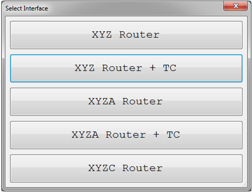
Figure 23
After loading the interface and launching the Radonix software, you must configure the Tool Changer settings. Open the Setting window and navigate to the ToolChanger branch. All related settings for the tool changer live here.
Warning:The ToolChanger topic fully documents every automatic tool change parameter and controller feature. You may need to adjust additional options there to suit your machine.
Next, choose your machine’s tool change method by setting the Type variable in the ToolChanger branch. (See ToolChanger for details on each method.)
Then configure the required digital inputs and outputs:
- Under System ▶ InPorts, enable and link each input. For each pin set:
- Enabled = True
- Select the correct Link (PNP vs NPN)
- Set NC if the input is Normally Closed
- You need five inputs, typically wired to:
- T-ToolHolder,1 (function)
- T-ToolHeightSensorPin
- T-HSD-S1Pin or T-ToolSensorPin, T-TEKNO-S2Pin, T-CC-S1Pin
- T-HSD-S2Pin or T-CC-S2Pin, T-TEKNO-S1Pin, T-ToolHolderSensorPin
- T-HSD-S3Pin or T-CC-S3Pin, T-TEKNO-S3Pin, T-SpindleRotationSensorPin, T-InverterStopPin
Note: Default input mappings are preconfigured.
- Under System ▶ OutPorts, enable and link each output:
- Enabled = True
- Link = OutPort
- NC if Normally Closed
- Two outputs are required:
- T-ToolHolderPin
- T-ToolCleanerPin
Once I/O is set, return to the ToolChanger branch and adjust the remaining variables as needed (see ToolChanger for full details).
Next, define each tool’s park coordinates under ToolChanger ▶ Tools. Home your machine, jog the spindle to each tool pocket, and save the absolute XYZ for every station (Figure 24).
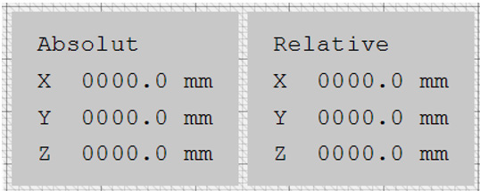
Figure 24
Finally, perform tool‐height calibration. Ensure T-ToolHeightSensorPin is enabled, then enter the sensor’s XYZ coordinates under ToolChanger ▶ ToolHeightSensor.
Warning:
- For general use, set ToolReference to 0.
- If you prefer manual height entry, set ToolReference to your spindle collet offset.
- Always complete height calibration after saving the park positions.