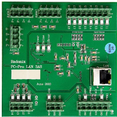
Pro-LAN 3AS
How to Wire PC-Pro LAN 3AS Series Controllers to Various Servo Drives
The 3AS series controllers (also known as step motor controllers) can drive servos just like the 2A, 4A and 6A series “servo” controllers. The main differences between the step and servo versions are:
- Maximum output pulse (PWM) frequency per axis
- Pinout / connector wiring for each axis
Below we explain both in detail, and show how you can adapt any servo drive (e.g. Delta ASDA-B2) to a Radonix 3AS controller.
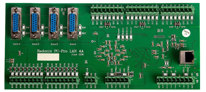
- Servo series: max PWM output = 500 kHz per axis
- Step series: max PWM output = 40 kHz per axis
Since the servo series can output 12.5× more pulses, if you replace a servo controller with a step controller you must increase the electronic gearbox ratio by 12.5× in the drive parameters. For example, with Delta B2-series 3000 rpm servos, multiply the existing electronic gear ratio by 12.5 × 16 (the default 16:1 gearbox) to match the step controller speed.
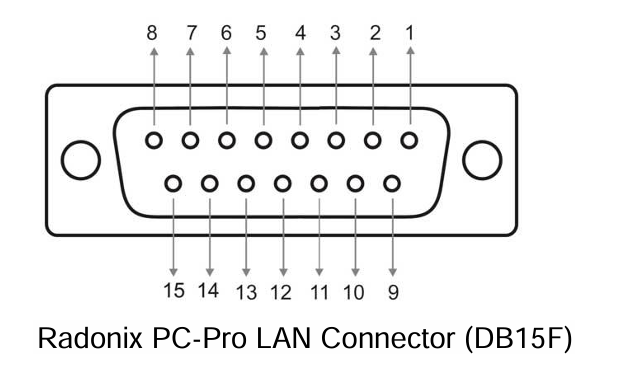
Each axis connector is a DB15-F (15-pin female D-sub). Pins 2–5 are used for PULSE and DIRECTION, the remaining pins either carry power or I/O. Below is the description of each pin on the servo connector, and how to map it into the Radonix 3AS controller. With this you can hook up any brand of drive.
-
Pin 1: +24 VDC
- Servo: digital inputs share a COM pin that must be tied to +24 VDC.
- Step: connect controller +24 V output directly to this pin.
-
Pin 2: Direction –
- Step controllers call this D–.
- Connect to the drive’s D– input.
-
Pin 3: Direction +
- Step controllers call this D+.
- Connect to the drive’s D+ input.
-
Pin 4: Pulse –
- Step controllers call this P–.
- Connect to the drive’s P– input.
-
Pin 5: Pulse +
- Step controllers call this P+.
- Connect to the drive’s P+ input.
-
Pin 6: Servo ON (Enable)
- Step: wire any spare digital output (O.1–O.4) → this pin, and in software set that output as ControlStatusPin, so that the drive arms when the controller goes online.
- You can also tie it high in the drive parameters to save an output.
-
Pin 7: Servo Ready
- Servo: DO+ / DO– pair.
- Step: tie DO+ → any spare digital input (I.1–I.8), and configure that input as Emergency with NC=True so that loss of ready trips an emergency.
- If inputs are limited, you may wire all ready signals in series so they share one input.
-
Pin 8: Encoder Zero
- Not used by step controllers. Leave unconnected.
-
Pin 9: Alarm Reset
- Step: wire any spare digital output (O.1–O.4) → this pin, and set that output as ClearAlarmPin.
- In the UI add a button linked to ClearAlarm, so pressing it issues the reset to all drives.
10.–15. Pins 10–15: Ground (GND)
- Most servo drives have CW/CCW limit or EL (emergency limit) on these.
- On step controllers you can either:
- Leave them unpopulated and set them Normally Open, or remove them.
- Tie them all to GND to disable limits.
- Wire individual limit sensors or switches if needed.
- You may also use one of these grounds to complete the DO– circuit for Ready.
Summary Table: PC-Pro LAN 4A ↔ 3AS Pin Mapping
| Pin | 4A Function | 3AS Label |
|---|---|---|
| 1 | VCC +24 V | * (24 V) |
| 2 | Direction – | D– |
| 3 | Direction + | D+ |
| 4 | Pulse – | P– |
| 5 | Pulse + | P+ |
| 6 | Servo On | O.1–O.4 (ControlStatusPin) |
| 7 | Ready | I.1–I.8 (Emergency) |
| 8 | Encoder Zero | Not Connected |
| 9 | Alarm Reset | O.1–O.4 (ClearAlarmPin) |
| 10 | Ground | GND |
| 11 | Ground | GND |
| 12 | Ground | GND |
| 13 | Ground | GND |
| 14 | Ground | GND |
| 15 | Ground | GND |
Example: Delta ASDA-B2 Drive
| 3AS Label | Description | ASDA-B2 Pin |
|---|---|---|
* (24 V) | VCC +24 V | 11 |
| D– | Direction – | 37 |
| D+ | Direction + | 39 |
| P– | Pulse – | 41 |
| P+ | Pulse + | 43 |
| O.1–O.4 (ControlStatusPin) | Servo On | 9 |
| I.1–I.8 (Emergency) | (DO+) Ready | 7 |
| Not Connected | Encoder Zero | 44 |
| O.1–O.4 (ClearAlarmPin) | Alarm Reset | 33 |
| GND | CW Limit | 32 |
| GND | CCW Limit | 31 |
| GND | Emergency | 30 |
| GND | (DO–) Ready | 6 |