Step-by-Step Guide
1. XY Cutter Interface (DC Motor-Controlled Z Axis)
The XY Cutter interface is designed for machines using DC motors to control the Z Axis. In this setup:
- The Z Axis is controlled via output links:
- C-Zfree,1 for upward movement.
- C-Zfree,-1 for downward movement.
This simple control method does not involve pulse and direction signals, making it suitable for basic XY cutting machines. Operators can activate the outputs to move the Z Axis up or down as required.
2. XYZ Cutter Interface (Manual Stepper/Servo-Controlled Z Axis)
The XYZ Cutter interface is intended for machines using stepper or servo motors in manual mode. In this configuration:
- The Z Axis is controlled via pulse and direction signals, directly connecting to the Axis control pins.
- Operators can manually adjust the Z Axis position during toolpath execution to ensure the cutting tool (e.g., plasma torch) maintains the correct height from the workpiece surface.
This interface is particularly suited for applications where manual intervention is required to maintain precision during operation.
3. XYZ Cutter + THC Interface (Automatic Stepper/Servo-Controlled Z Axis)
The XYZ Cutter + THC interface is designed for machines where the Z Axis operates in automatic mode, managed by the THC (Torch Height Control) module. This configuration relies on feedback from the plasma unit's arc voltage:
- Feedback Voltage Control:
- As the plasma arc length increases, the feedback voltage from the plasma unit rises.
- Conversely, as the arc length decreases, the feedback voltage drops.
- Automatic Adjustment:
- The Z Axis dynamically adjusts its height based on the feedback voltage to maintain the optimal cutting distance.
The THC module ensures real-time adjustments, providing consistent and precise cutting performance. This interface is ideal for high-precision plasma cutting machines where automatic height control is critical.
Introduction
CNC cutting machines are typically designed for cutting two-dimensional designs and include two axes, X and Y, used for cutting materials such as metal, wood, plastic, and others. These machines may also feature a Z axis, which adjusts the cutting nozzle's distance from the workpiece surface. However, the Z-axis control in these machines is usually not automated or performed via G-Code; instead, the operator must manually adjust the nozzle's distance. The Z-axis motors can be AC, DC, stepper, or servo motors, and depending on the type and thickness of the materials, the cutting nozzle can be equipped with air gas, plasma, waterjet, laser, etc.
Radonix Interfaces for CNC Cutting Machines
Radonix, a manufacturer of CNC controllers, has thoroughly analyzed these types of machines and designed dedicated interfaces for them. The XY-Cutter and XYZ-Cutter interfaces are specifically designed for these machines:
- XY-Cutter Interface: For machines without a Z-axis or with AC and DC motors for the Z-axis.
- XYZ-Cutter Interface: For machines with a Z-axis and stepper or servo motors.
In these interfaces, all inputs, outputs, and functions are designated with the prefix C-.
Key Features of Radonix Interfaces
- Direct execution of design files without the need for conversion to G-Code.
- The ability to select individual parts from a large file and define the sequence and direction of cutting for each piece.
- Design editing in the software with features such as Scale, Rotate, and Flip.
- Software-based correction of workpiece misalignment, especially for heavy sheets.
- Separate pauses for before, during, and after cutting.
- Reverse execution of designs and the ability to run demos without activating the cutting output.
- Execution of 2D designs on cylindrical surfaces such as pipes.
These features enable Radonix interfaces to provide more precise control and greater efficiency in the cutting process.
This interface is called XY Cutter
Radonix provides three distinct interfaces for XY Cutter machines, categorized based on the strategy and functionality of the Z Axis. This division ensures compatibility with various machine types and operational requirements. Below is a detailed explanation of these interfaces:
1. XY Cutter Interface (DC Motor-Controlled Z Axis)
The XY Cutter interface is designed for machines using DC motors to control the Z Axis. In this setup:
- The Z Axis is controlled via output links:
- C-Zfree,1 for upward movement.
- C-Zfree,-1 for downward movement.
This simple control method does not involve pulse and direction signals, making it suitable for basic XY cutting machines. Operators can activate the outputs to move the Z Axis up or down as required.
2. XYZ Cutter Interface (Manual Stepper/Servo-Controlled Z Axis)
The XYZ Cutter interface is intended for machines using stepper or servo motors in manual mode. In this configuration:
- The Z Axis is controlled via pulse and direction signals, directly connecting to the Axis control pins.
- Operators can manually adjust the Z Axis position during toolpath execution to ensure the cutting tool (e.g., plasma torch) maintains the correct height from the workpiece surface.
This interface is particularly suited for applications where manual intervention is required to maintain precision during operation.
3. XYZ Cutter + THC Interface (Automatic Stepper/Servo-Controlled Z Axis)
The XYZ Cutter + THC interface is designed for machines where the Z Axis operates in automatic mode, managed by the THC (Torch Height Control) module. This configuration relies on feedback from the plasma unit's arc voltage:
- Feedback Voltage Control:
- As the plasma arc length increases, the feedback voltage from the plasma unit rises.
- Conversely, as the arc length decreases, the feedback voltage drops.
- Automatic Adjustment:
- The Z Axis dynamically adjusts its height based on the feedback voltage to maintain the optimal cutting distance.
The THC module ensures real-time adjustments, providing consistent and precise cutting performance. This interface is ideal for high-precision plasma cutting machines where automatic height control is critical.
Summary
Radonix's interfaces for XY Cutter machines are tailored to meet various operational needs:
- XY Cutter Interface: For basic machines with DC motor-controlled Z Axis, using C-Zfree,1 and C-Zfree,-1 outputs for up/down movement.
- XYZ Cutter Interface: For stepper/servo motors with manual operator control of the Z Axis via pulse and direction signals.
- XYZ Cutter + THC Interface: For stepper/servo motors with plasma arc feedback, dynamically managed by the Torch Height Control (THC) module.
These interfaces ensure Radonix controllers provide versatility, precision, and adaptability for a wide range of cutting applications.
Get Start
Workspace Descriptions
1- Study about different part of interface which is named and indicated in photo it means that you should get familiar with all elements like Buttons , screen , bars , volume , values , … anything on interface you have accesses
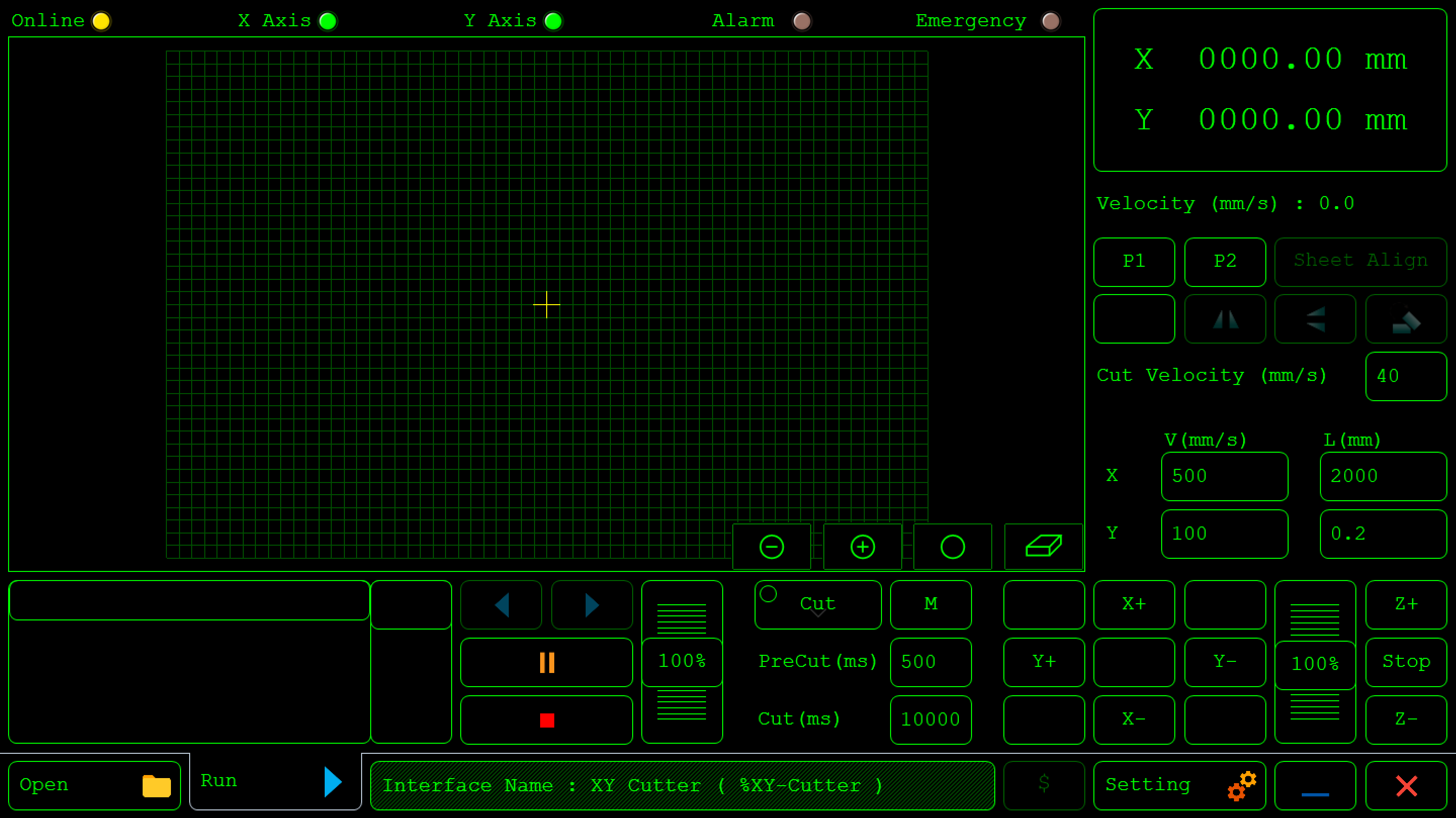
Top Status Bar

- Online (Yellow Light): Indicates the machine's connection status. Yellow may mean a standby mode or that it's online. If the controller and software are connected, it is on. If the controller and software are not connected, it is off or gray .
- X Axis, Y Axis, (Green Lights): These lights show the operational status of each axis. Green typically means these axes are ready. If an axis is active, it turns on. If an axis is inactive, it remains off and appears gray .
- Alarm, Emergency : Indicators for critical safety statuses. When activated, they may change color to red to signal an alarm, emergency stop.
**Position **
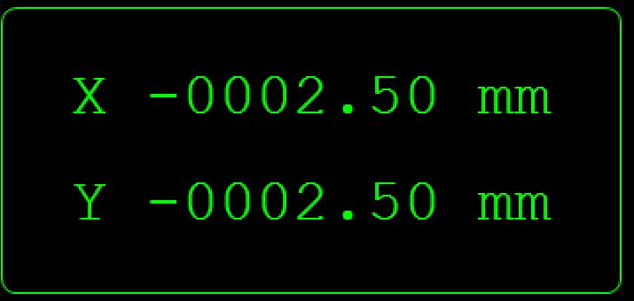
This position is shown based on where the reference point has been selected.
- Velocity (Below Relative Position): Shows the current operational speed in mm/s, useful for monitoring real-time cutting or movement speeds.

**Reference **
Radonix interfaces offer a reference , allowing operators to redefine the reference point at any moment during the operation. This feature enhances flexibility and precision in workflows, making it suitable for diverse applications.
it means that operator can change start point of workpiece on the table.

- Cut Velocity : If the operator needs to manually cut a part of the piece without using a design file, they can activate the C-CutPin output and use the manual movement keys (JOG) to perform the operation. In this mode, the machine’s movement speed is determined by this parameter, which is measured in millimeters per second (mm/s).

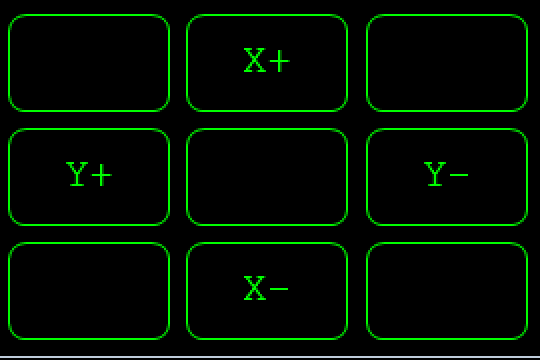
- Manual Jogging Controls :
-
Arrows (X+, X-, Y+, Y-): These buttons are used for manual axis movement (Jog) and can operate in two modes: Continuous and Incremental.
-
In Continuous mode, or when the Jog key is held down, the selected axis moves at the specified speed.
-
In Incremental mode, each press of the Jog key moves the selected axis by the set distance.
-
You can switch the jog mode by pressing this button according fig 01-05 and it will change to figure 01-06, changing from continuous to incremental movement. This means you can define a value in this section according fig 01-07 which has been indicated in red area , and after pressing the coordinate axis jog, the axis will move by the amount you have entered.


Feed Rate and Tool Parameters (Lower Right Panel)
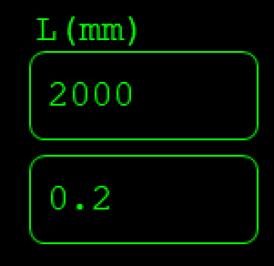
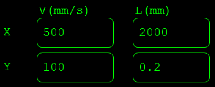
- V (mm/s) and Step**(mm)**: Input fields for setting feed rates and movement limits along each axis. "V" controls the velocity (or speed) in mm/s, and "L" could define the step size for each manual jog.
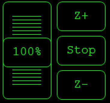
- Scroll (Vertical Slider on Bottom Right ):According to figure 01-08 which is demarcated with red area or Allows for real-time adjustment of the feed rate or speed as a percentage. This control can quickly change the speed without directly altering program values.
Main Program Controls
- Settings (Gear Icon): Opens the configuration menu, where detailed settings for the CNC machine can be adjusted.

- The Exit icon allows you to close the program
- The Minus icon lets you minimize it.
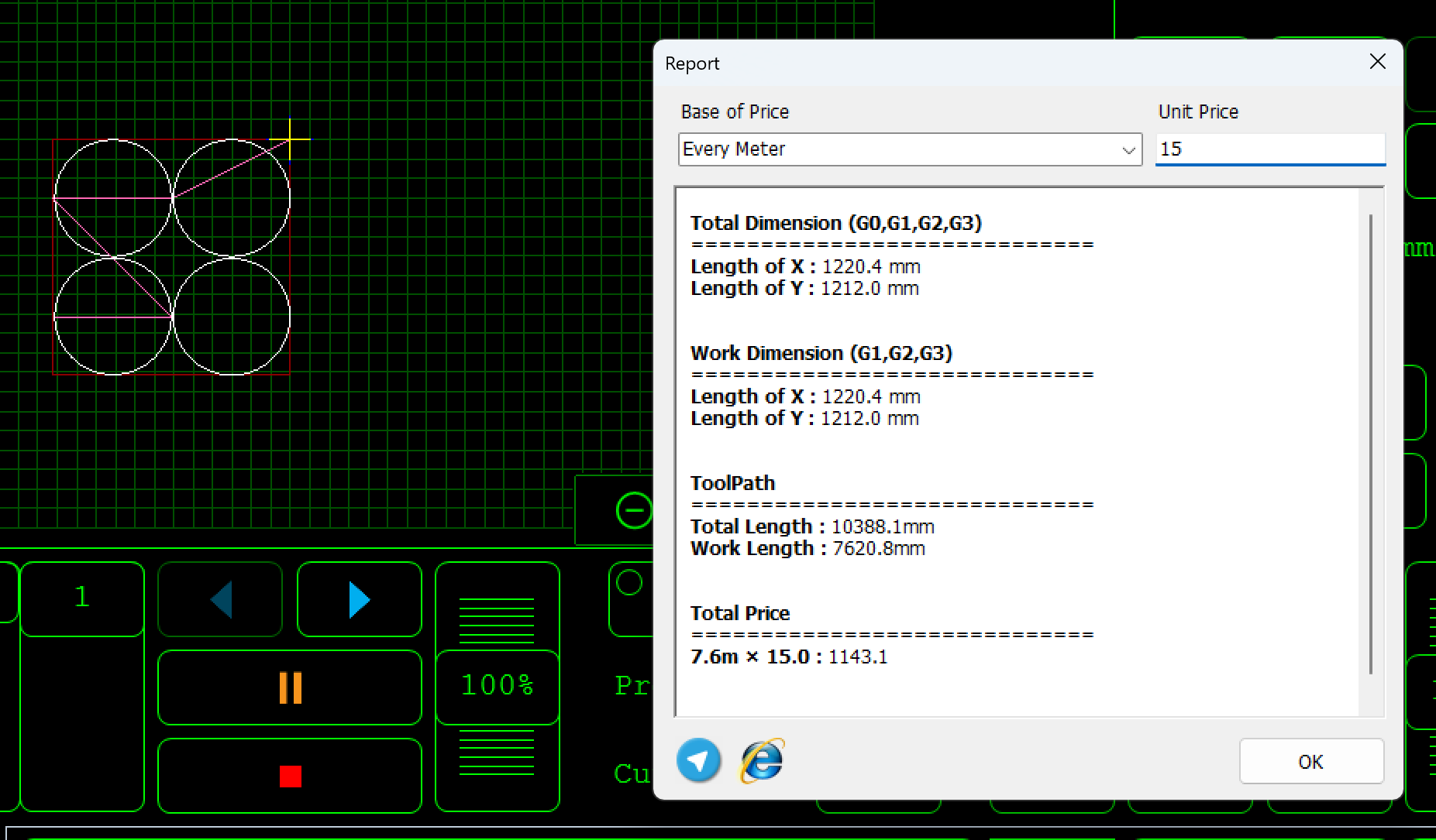
- The $ icon create a report from the workpiece and operator can estimate the price
Interface specification

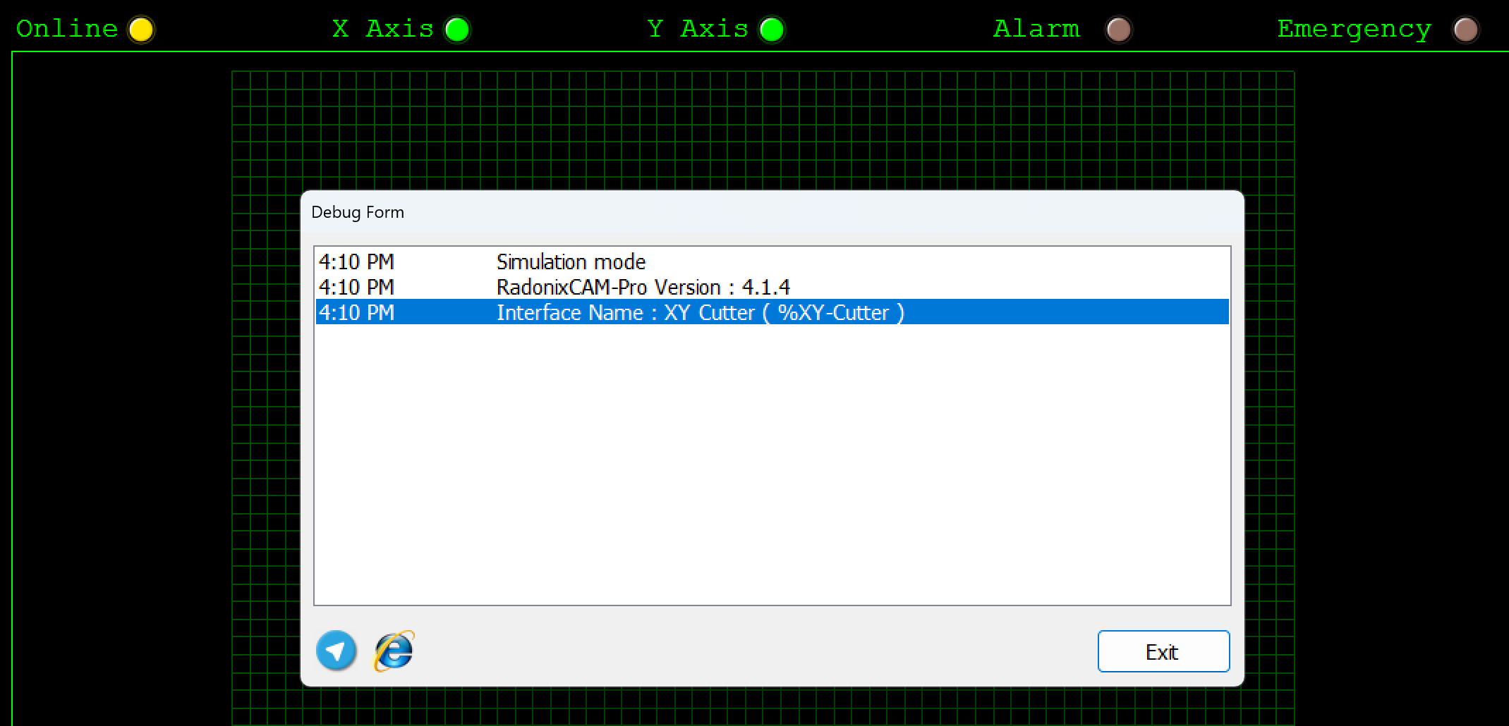
This section of the interface displays the current status and features of the system. It also updates to show alarms and processes every second. For a detailed report, double-click on this section.
Main Program Controls (Bottom Center)
- Open File (Folder Icon): Opens a file dialog for loading a CAM (Computer-Aided Manufacturing) file, typically a G-code or DXF program.
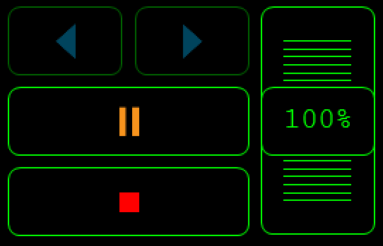
This section is dedicated to controlling G-Code execution:
- RUN: This button starts the G-Code process.
- Backward:The Backward button provides operators the ability to step back within the G-Code toolpath execution process. This feature is essential for troubleshooting, rechecking, or re-executing specific portions of the G-Code.
- Pause: This button halts the toolpath.
- Reset: This button resets the toolpath.
Inports
In this section, we will examine the configuration of the Inputs.
Essentially, when the Inports branch is opened, these settings will appear.
Setting Up Inputs: General Overview
Configuring inputs in our CNC system is an essential step to ensure smooth operation, precise control, and safety. Inputs can be categorized into two main types based on their configuration and purpose: Hardware-Based Inputs and Software-Based Inputs. This flexibility allows the system to adapt to a wide range of applications and machine requirements.
1. Hardware-Based Inputs
Hardware inputs involve physical devices connected to the controller, enabling direct interaction with the machine's environment. These inputs are crucial for safety, machine control, and real-time feedback.
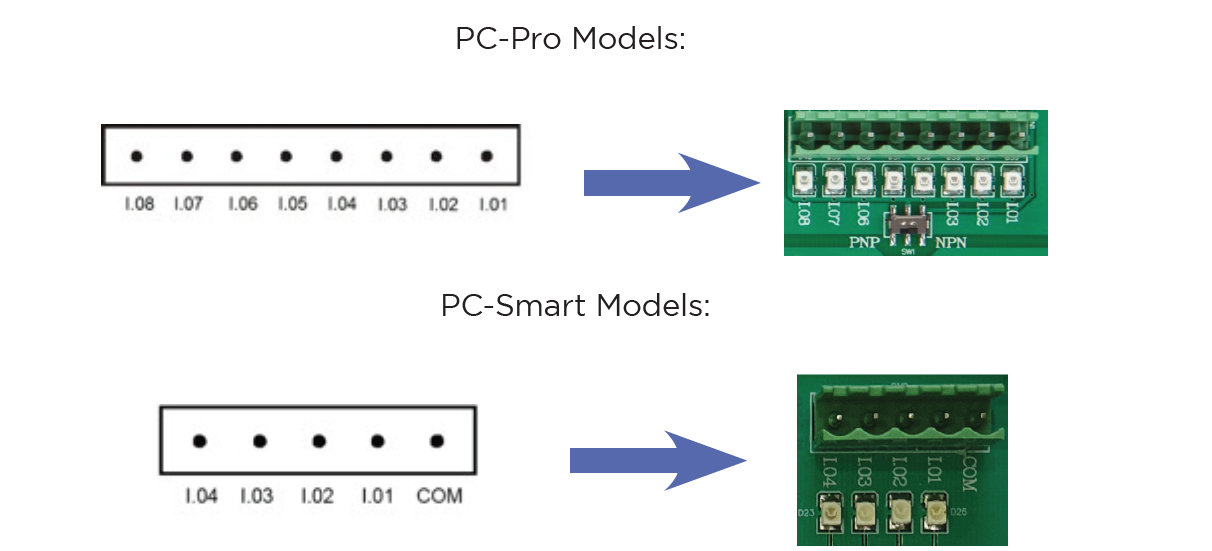
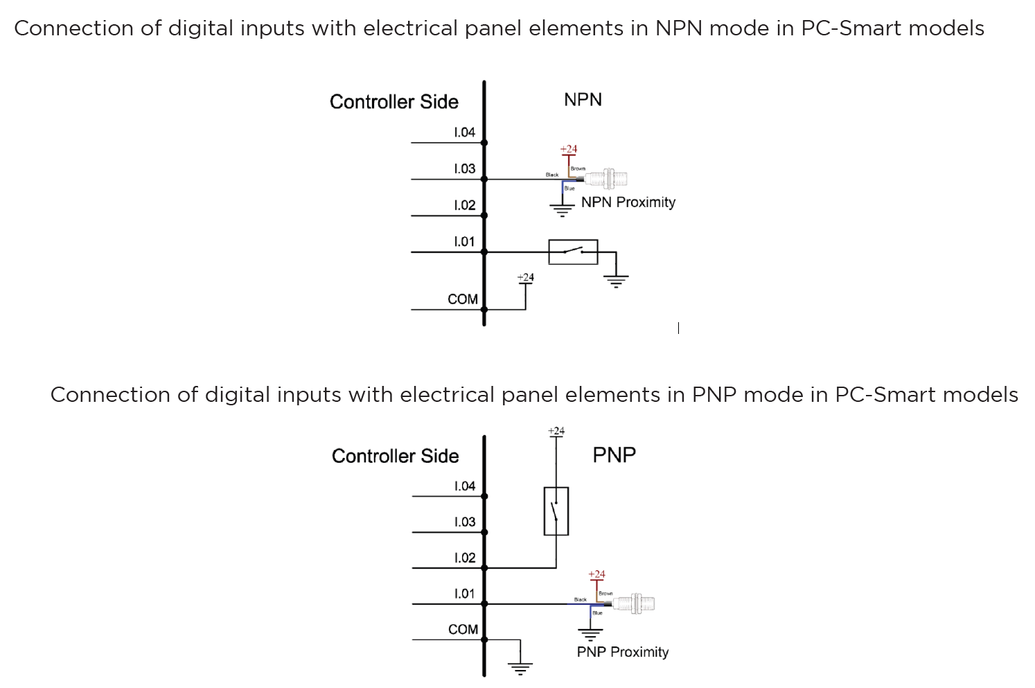
The digital inputs of Radonix controllers are named as I.[n], where n is a number greater than zero and represents the input number. These inputs are isolated by optical couplers and have low noise tolerance due to their low impedance.
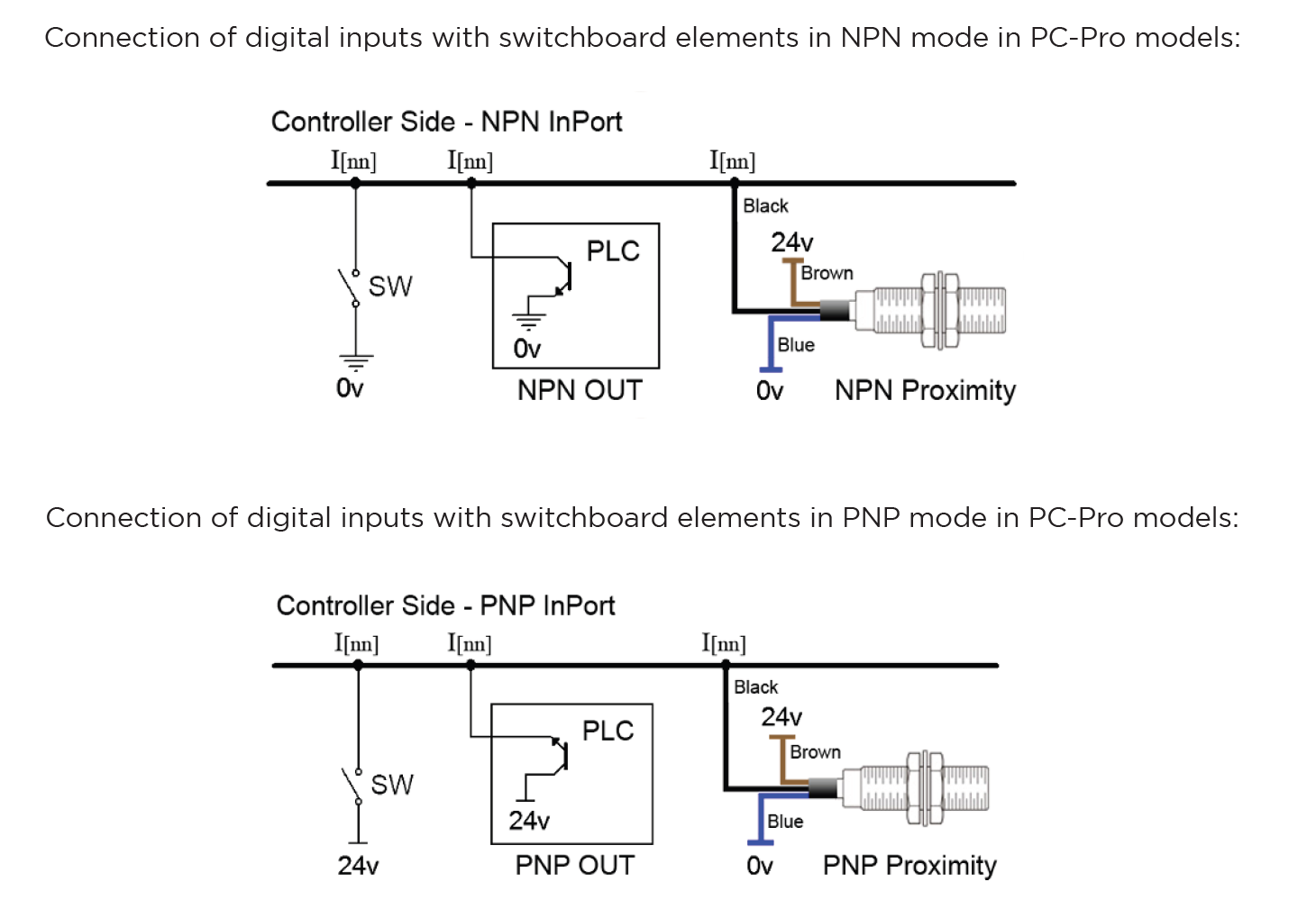
The digital inputs on Radonix controllers have the capability to switch between NPN and PNP modes depending on the output of the device or sensor. The mode changeover switch must be set to PNP position for devices with PNP output and NPN position for devices with NPN output.
In various branches of industrial automation, there are equivalent terms for PNP and NPN. Someexamples of these terms include:NPN = Sink = Low ActivePNP = Source = High Active
Switching Between PNP and NPN Modes in Radonix Systems
The ability to switch between PNP (positive logic) and NPN (negative logic) modes in Radonix controllers depends on the specific board model being used. This flexibility allows the system to be compatible with different wiring and sensor configurations.
- PC Pro LAN:
- A small DIP switch is present on the board.
- This switch allows users to toggle between PNP and NPN modes.
- How to Use:
-
Locate the DIP switch on the board.
-
Toggle the switch to the desired mode (PNP or NPN).
-
Ensure the board is powered off before making changes to prevent damage.
-
- PC Smart:
-
Instead of a DIP switch, the PC Smart model uses a Come Pin for each set of 4 input pins.
-
This pin allows you to define the input logic (PNP or NPN) for the corresponding inputs.
-
How to Use:
-
Connect the Come Pin to the appropriate voltage (positive for PNP or ground for NPN).
1.PNP Mode (Source Mode):
- If the COM pin is connected to 0V, the input pins will be triggered (turned ON) by a 24V signal.
- In this configuration, the sensor’s output wire must provide a 24V signal to activate the input.
2.NPN Mode (Sink Mode):
- If the COM pin is connected to 24V, the input pins will be triggered (turned ON) by a 0V signal.
- In this configuration, the sensor’s output wire must pull the input to 0V to activate it.
- If the COM pin is connected to 0V, the input pins will be triggered (turned ON) by a 24V signal.
-
Each group of 4 input pins has its own Come Pin, allowing for mixed configurations within the same board.
-
-
Examples of Hardware Inputs:
- Limit Switches: Define physical boundaries for axis movement.
- Home Sensors: Establish the reference (Home) position for the machine most of them are Proximity
- Emergency Stop Buttons: Ensure immediate halting of operations in emergencies.
- Other Proximity Sensors: Detect objects or tools in the machine's workspace.
- Push Buttons and Selector Switches: Trigger specific machine functions or modes.
- Scanners: Measure or detect specific properties, often used in specialized processes such as Glass or gold CNC operations.
Configuration Process:
- Connection: Physically connect the hardware component (e.g., a switch or sensor) to the designated input pin on the controller.
- Input Definition: Use the controller software to define the role of the input (e.g.,
HomePin,LimitPin, or a custom input for specific functions). - Polarity Settings:
- Set the input type as Normally Open (NO) or Normally Closed (NC) based on the connected hardware's default state.
- For example:
- An NC emergency stop button remains active (closed) until pressed.
- An NO proximity sensor activates (closes) only when an object is detected.
2. Software-Based Inputs
Software-Based Inputs provide simple logical functionality to configure arbitrary links and integrate them with related physical hardware .They facilitate quick and simple installation without the need for microprogramming. Users can simply select options from a list and configure settings to maximize efficiency.
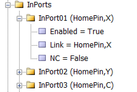
As illustrated in the figure, each input is divided into three sub-branches, as detailed below:
- Enable: This sub-branch can be set to two values: True or False.
- Link: Specifies the duty or task that needs to be performed or checked. This includes any device that can serve as an input, such as sensors, buttons, and switches.
- NC: Determines whether the specific input is Normally Open (NO) or Normally Closed (NC).
Examples of Software Inputs:
- Virtual Limit Switches:
- Use software parameters to define axis movement boundaries based on the machine's table size.
- Logical Triggers: Define conditional triggers for specific operations (e.g., When the axis reaches the limit switch ).
- Simulated Inputs: Use for testing or scenarios where physical components are unavailable.
Configuration Process:
-
Access Configuration Interface:
- Open the controller's software settings to manage inputs.
-
Define Parameters:
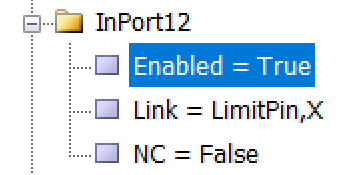
As an example to set limit Switch :
-
setting —→ System —→ In ports —→ Enabled= True
Linked = LimitPin,X
NC= True
-
Configure additional logical conditions for interlocks or simulations.
- Validate Settings:
- Test the software by CAM Pro TEST input configurations to ensure proper functionality and safety.
Outputs
In this section, we will examine the configuration of the Outputs.
Setting Up Inputs: General Overview
In Radonix systems, Outports are critical components that manage the output signals controlling various peripherals, such as relays, actuators, alarms, and other devices. Outputs can be categorized into two main types based on their configuration and purpose: Hardware-Based Inputs and **Software-Based outputs.**This flexibility allows the system to adapt to a wide range of applications and machine requirements.
1. Hardware-Based Outputs
Hardware outputs involve physical signals sent from the controller to external devices, enabling direct control of the machine’s environment. These outputs are critical for operational safety, machine actuation, and real-time command execution, ensuring efficient workflow and coordination within the CNC system.
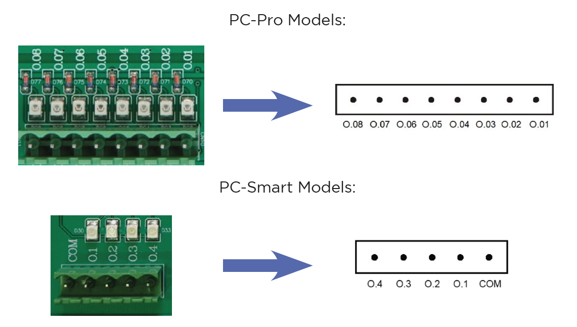
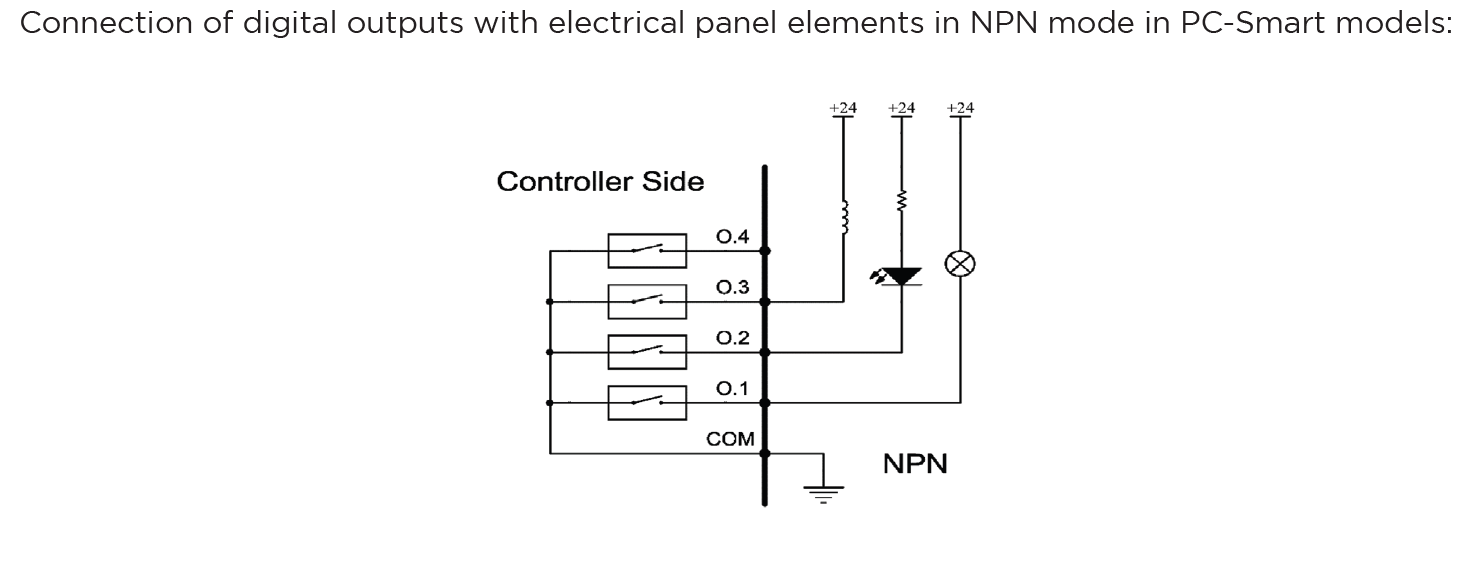
The digital outputs of Radonix controllers are named O.[n], where n is a numerical identifier greater than zero and represents the output number .
Radonix controllers incorporate robust protection mechanisms for Outports to ensure durability, safety, and reliability. These mechanisms vary between different models, specifically the PC-Pro and PC-Smart boards, each with distinct protection features and failure handling processes.
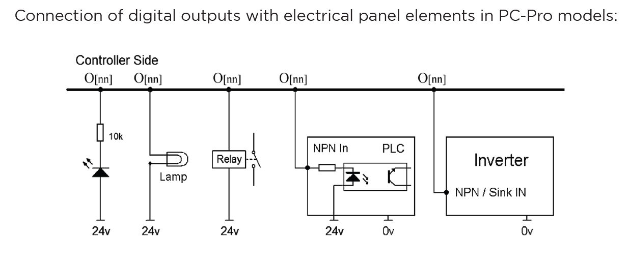
Output Behavior in PC-Pro LAN Models
-
The PC-Pro LAN model outputs are fixed in NPN mode.
-
How It Works:
- When an output is ON, it provides 0 volts by pulling the signal to ground.
- When an output is OFF, it is in a high-impedance state, effectively disconnecting the circuit.
-
Wiring Consideration:
- Connected devices must be compatible with NPN logic, where the load receives voltage from a positive source and is activated when the output pulls the circuit to ground.
Output Behavior in PC-Smart Models
-
The PC-Smart model offers a flexible configuration where outputs can operate in PNP mode or NPN mode, depending on the connection of the COM Pin.
-
How It Works:
- The voltage provided by the outputs depends on what is connected to the COM Pin:
- COM Pin Connected to 24V: Outputs will provide 24 volts when activated.
- COM Pin Connected to Ground: Outputs will provide 0 volts when activated (NPN mode).
- The voltage provided by the outputs depends on what is connected to the COM Pin:
-
Flexibility:
- This design allows PC-Smart models to adapt to different wiring requirements and device logic preferences.

Configuration Process for Outputs:
- Connection:
- Physically connect the hardware component (e.g., relay, electric valve , Barke , alarm) to the designated output pin on the controller.
- Ensure proper wiring based on the required logic (PNP or NPN) and voltage compatibility.
- Output Definition:
- Use the controller software to define the role of the output (e.g.,
C-CutPin,Brake, or a custom output for specific functions). - Assign the output to its intended device or operation in the system settings.
- Use the controller software to define the role of the output (e.g.,
- Logic Settings:
- Set the output logic based on the connected device's requirements:
- Active High (PNP): The output sends voltage (e.g., 24V) when activated.
- Active Low (NPN): The output pulls the signal to ground (0V) when activated.
- Set the output logic based on the connected device's requirements:
- Testing and Validation:
- After configuring, test the output to ensure it operates as intended in CAM Pro Test application.
- Use a multimeter or other diagnostic tools to verify output voltage and behavior.
2. Software-Based Outputs
Software-Based Outputs provide simple logical functionality to configure and integrate them with related physical hardware. These features are crucial for enhancing control capabilities. They facilitate quick and simple installation without the need for microprogramming. Users can simply select options from a list and configure settings to maximize efficiency.
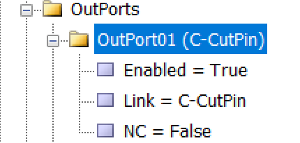
As illustrated in the figure, each output is divided into three sub-branches, as detailed below:
- Enable: This sub-branch can be set to two values: True or False.
- Link: Specifies the duty or task that needs to be performed or checked. This includes any device that can serve as an output, such as actuators, lights, and alarms.
- NC: Determines whether the specific output is Normally Open (NO) or Normally Closed (NC).
Examples of Software Outputs:
- Virtual Relays:
- Use software parameters to define activation boundaries for devices based on operational needs.
- Logical Triggers: Define conditional triggers for activating specific outputs (e.g., alarms or Relay for specific function ).
- Simulated Outputs: Employ these for testing or in scenarios where physical components are not available.
Configuration Process:
- Access the Configuration Interface:
- Navigate to the controller's software settings to manage outputs.
- Define Parameters:
-
To configure an output like an order to forward the VFD, enter parameters.
-
setting —→ System —→ Outports —→ Enabled= True
Linked = C-CutPin
NC= True
-
- Validate Settings:
- Test the configured software outputs to ensure they function correctly and safely, verifying their effectiveness in real-world applications.
Setting Up Inputs: Simple and Intuitive Configuration
In Radonix system, configuring inputs or Outputs is designed to be as user-friendly as possible, without requiring any microprogramming or advanced technical knowledge. All you need to do is navigate to the Inputs section of the controller interface, open the settings drawer, and select the item you need to configure. The same process applies to other sections, such as Outputs or any other functional areas.
Step-by-Step Configuration Process
- Access the Desired Section:
- Go to the section you want to configure, such as Inputs or Outputs, depending on the functionality you are setting up.
- Open the Settings Drawer:
- Within the selected section, locate the specific input branch or subsection.
- Click or expand the settings drawer to reveal the available options.
- Select the Required Item:
- Choose the input type or functionality you want to configure (e.g., limit switch, home sensor, emergency stop, or custom inputs).
- Define the specific role for the input, such as
C-ZFreePin,1
- Set Parameters Easily:
- Adjust the necessary parameters, such as polarity (Normally Open or Normally Closed), response delays, or logical behavior, directly from the interface.
- Save and Test:
- Save your settings and validate them through the controller interface to ensure everything is functioning as intended.
- In the end in order to finalizing you have to close program to save everything
Installation and Setup Process for Radonix CNC Controller
Radonix recommends following this detailed step-by-step guide for installing and configuring a Radonix CNC controller. The process encompasses everything from wiring the hardware to setting parameters in the software. This approach aims to guarantee a seamless installation experience for customers, addressing all critical components.
Wiring Components for a Radonix CNC Controller
Proper wiring is the foundation of a reliable and high-performing CNC machine. A professional approach to wiring ensures seamless communication between the Radonix controller, servo or stepper motors, sensors, VFDs (Variable Frequency Drives), and other peripherals. This guide provides expert advice on wiring all components, including selecting appropriate power supplies, ensuring safety, and achieving optimal performance.
1. Main Components Overview
A typical CNC system includes the following components, all of which require precise and secure wiring:
- Radonix CNC Controller: The central control unit.
- Servo or Stepper Motors: Responsible for axis movement.
- Variable Frequency Drive (VFD): Controls the spindle motor.
- Sensors:
- Home Sensors for axis referencing.
- Limit Switches for boundary control.
- Home Sensors for axis referencing.
- Limit Switches for boundary control.
- Emergency Stop (E-Stop): Ensures immediate shutdown during emergencies.
- Power Supplies: Provides regulated power for different components.
- Peripheral Outputs: Includes relays, coolant pumps, and alarms.
2. Wiring the Main Power Supply
Choosing the suitable Power Supply
-
Controller Power Supply:
It is recommended to use 24V switching power supplies to power the Radonix controllers. Calculating Power Supply Current To determine the required power supply current in the electrical panel, the current consumption of each element connected to the power supply must be calculated. For example, if there are 4 relays, 3 pneumatic solenoid valves, and a controller in a switchboard, the current consumption can be determined using Ohm’s law (V=I*R). The electric currents should be calculated and their sum considered as the current of the power supply, along with a confidence factor of a few percent. For example, if the current consumption of the relays is 0.1A and that of the solenoid valves is 0.25A, the total current can be calculated as follows: Total current = controller current + relay current + solenoid valve current IT = 0.5 + 4 * 0.1 + 3 * 0.25 = 1.65A
3. Anti-Noise Measures for CNC Wiring
Electromagnetic interference (EMI) or electrical noise is a common issue in CNC systems, particularly when wiring sensitive components like controllers, servo drives, and sensors. Noise can disrupt signals, cause erratic machine behavior, and even damage components over time. Implementing robust anti-noise measures is critical for ensuring the reliable and precise operation of your CNC machine.
Sources of Electrical Noise
- High-Frequency Devices:
- Variable Frequency Drives (VFDs)- (In Related Machines)
- Switching power supplies
- High-Power Components:
- Spindle motors - (In Related Machines )
- Servo and stepper motors
- Long Cables:
- Longer cables act as antennas, picking up EMI.
- Proximity to Power Lines:
- Signal and power cables running close together can cause interference.
Key Anti-Noise Measures
1. Use Shielded Cables
- Purpose: Shielded cables reduce the effect of electromagnetic interference on sensitive signals.
- Implementation:
- Use twisted-pair shielded cables for signal lines like Pulse+, Pulse-, Direction+, Direction-, and sensor signals.
- Connect the shield to ground at one end only to avoid ground loops.
2. Separate Signal and Power Cables
- Purpose: Prevent high-power cables from inducing noise in low-power signal cables.
- Implementation:
- Route signal cables (e.g., sensor and control signals) separately from power cables (e.g., motor power and VFD output).
- Maintain at least 10-15 cm of separation between these cable types.
- Use different cable trays or conduits for power and signal lines.
3. Proper Grounding
- Purpose: A well-designed grounding system minimizes noise and protects components.
- Implementation:
- Create a central grounding point in the electrical box, often referred to as a grounding bus bar.
- Ensure all grounding wires (controller, drives, motors, etc.) connect to this central point.
- Avoid daisy-chaining ground connections, which can introduce noise.
4. Install Ferrite Beads
- Purpose: Ferrite beads filter out high-frequency noise on signal and power cables.
- Implementation:
- Clip ferrite beads onto signal and control cables near the controller or servo drives.
- Use multiple beads for particularly noisy environments.
5. Proper VFD Wiring
- Purpose: VFDs are a significant source of electrical noise and require special attention.
- Implementation:
- Use shielded cables between the VFD and spindle motor.
- Ground the cable shield at the VFD end.
- Install line filters or chokes on the VFD input and output to suppress noise.
6. Shorten Cable Lengths
- Purpose: Longer cables are more susceptible to picking up noise.
- Implementation:
- Keep cable lengths as short as possible without compromising flexibility.
- Avoid unnecessary slack or loops in the wiring.
7. Use Isolated Power Supplies
- Purpose: Prevent noise from one system affecting another.
- Implementation:
- Use separate, isolated power supplies for sensitive components like sensors, encoders, and the controller.
- Ensure power supplies are adequately rated and properly grounded.
8. Use Optical Isolation
- Purpose: Protect the controller from noise on external connections.
- Implementation:
- Use opto-isolators for connections to external devices like sensors, relays, or switches.
- Many Radonix controllers have built-in optical isolation for inputs and outputs.
9. Secure Connections
- Purpose: Loose connections can act as noise sources.
- Implementation:
- Check all connectors for tight and secure connections.
- Use locking connectors where possible to prevent accidental disconnections.
10. Line Filters and Surge Protectors
- Purpose: Suppress high-frequency noise and protect against voltage spikes.
- Implementation:
- Install EMI line filters on the AC mains supply.
- Use surge protectors on power inputs to the controller and VFD.
Software Configuration: Bringing the System to Life
Step 1: Install Radonix Cam Pro
- Download and install the software on your PC.
- Upon turning on the controller, observe the LEDs on the LAN port: one should remain steady, while the other blinks.
- Connect the Radonix controller to the computer via a LAN or USB cable.
Step 2: Initial Setup
- Open the software and initialize the system.
- Perform a factory reset to ensure default settings are applied.
Step 3: Configure Inputs
- Navigate to Settings > System > Inports.
- Assign roles to each input:
EmergencyStopfor the E-Stop button.HomePin, X/Y/Zfor home sensors.LimitPin, X/-Xfor limit switches.
- Test each input by activating it physically and observing the software response.
Step 4: Configure Outputs
- Navigate to Settings > System > Outports.
- Assign roles to each output:
C-CutPinfor turn on torch.C-ZfreePin,1for active a Relay to move axis Z upward .C-ZfreePin,-1for active a Relay to move axis Z downward .
- Test outputs by toggling them in the software and observing the connected devices.
Step 5: Axis Calibration
- Go to Settings > System > Calibration.
- Enter parameters for each axis:
- Steps per Unit: Based on lead screw pitch, motor steps, and encoder resolution.
- Max Travel: Define the maximum travel distance for each axis.
- Test calibration by commanding movements and measuring actual travel distances.
Emergency Stop (E-Stop)
A critical response mechanism in industrial settings used to halt machinery and equipment immediately in order to protect against imminent danger. This action is typically engaged through an emergency stop button or switch that, when activated, interrupts the power supply and ceases all operations, effectively minimizing the risk of accidents, injuries, or damage to the machinery and personnel.
Configurable Emergency Mode:
An advanced feature in control systems that allows users to define and set up custom emergency responses through the system settings. This mode can be programmed to engage different levels or types of responses depending on the nature and severity of the threat detected.
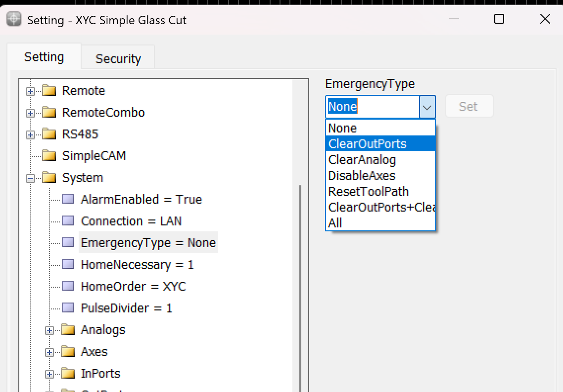
This variable is used to determine the operation that occurs when the Emergency button is pressed.
Emergency Type
- None: When this mode is selected, the machine operation is similar to a pause. The device stops all activities but cannot be resumed from the same point if this mode is triggered.
- ClearOutPorts: Activating this mode stops the axes and turns off all digital output ports of the controller. This ensures that no further commands affect the machine's operation until reset.
- ClearAnalog: This mode stops the axes and turns off all analog outputs. It's used to ensure that any variable outputs controlling aspects like tool pressure or spindle speed are deactivated.
- DisableAxes: In this emergency mode, the axes of the machine are stopped and become inactive, which means the motors that drive the axes are disengaged, allowing them to move freely if manually pushed but not under power.
- ResetToolPath: This mode stops the axes and resets the toolpath to the start of the program. This is useful in scenarios where the process needs to be started from the beginning, either to prevent damage or to correct an error.
- ClearOutPorts+ClearAnalog: This comprehensive emergency mode combines the effects of ClearOutPorts and ClearAnalog, stopping all digital and analog outputs, disabling the axes, freeing the motors, and resetting the toolpath to the first coordinate. This is effectively a full reset of the system's operating state.
- All: Selecting "All" activates all the above emergency responses, providing the maximum level of immediate system shutdown. All outputs, both digital and analog, are turned off; axes are stopped and freed; and the toolpath is reset.
Home Sensors
Home sensors are so crucial for positions it means that thanks to these sensors the position become meaningful , they are impact in defining table size the sensors are machine zero point or machine origin point when axis reach the sensors the controller detect them and it causes that a red table is created in Black Grid space so with this option each point in this area has its own position than sensors ın each axis
Indeed, home sensors are integral to the function and accuracy of CNC machines. Let's explore further how these sensors interact with the CNC controller and influence the machine workspace setup:
Role and Functionality of Home Sensors:
- Defining the Origin: Home sensors establish the machine's zero point or origin. This point serves as the reference for all other positions within the machine's operational space. It ensures that the machine knows the starting point for all axes (typically labeled X, Y, and Z).
- Impact on Table Size and Work Area Definition: The detection of the home position by these sensors directly impacts the definition of the machine’s table size. This is because the machine controller uses the origin point to calculate and define the extents of the machine’s operational area or table. The movements and operations of the machine are confined within these calculated boundaries to ensure precision and to prevent the machine from moving beyond its capable limits, which could cause damage or errors.
- Visualization on Controller Interface: When the home sensors are triggered, the CNC controller can visually depict this on its interface, often illustrated as a "red table" laid out on a "black grid" background. This visual representation helps operators to see and understand the active working area of the machine. It shows where tools can safely travel and operate, providing a clear demarcation of the workspace.
- Positional Accuracy: Each point within this defined red table area has a specific position relative to the machine’s origin point, determined by the home sensors on each axis. This arrangement allows for precise control over the machine's movements and operations, ensuring that every motion made by the machine is accurately accounted for relative to the origin, enhancing both the precision and reliability of the work performed.
- Operational Reliability: Regularly using home sensors to reestablish the machine’s origin point helps maintain operational accuracy and reliability, crucial for long-term consistent output, especially in precision-dependent applications.
Overall, home sensors not only provide a safety mechanism by defining the limits of machine operation but also enhance operational precision by establishing a clear and reliable reference point for all machining tasks. This setup ensures that every point within the operational area is accurately positioned relative to the origin, making the machine's functioning both predictable and precise.
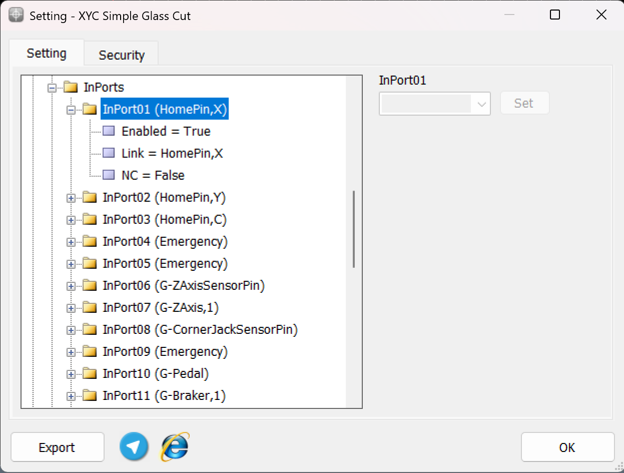
To ensure precise cessation of axis movement after issuing the Home command, the appropriate input links must be configured prior to pressing the Home button, as depicted in the above explanation. This configuration ensures that the machine accurately detects the home position for each axis.
For example:
-
The input HomePin,X is assigned to detect the X-axis home position. This means that when the X-axis sensor aligns in front of its designated home sensor, the system identifies it as the home position.
-
Similarly, other axes such as Y , C , Z require their respective input links, such as HomePin,Y or HomePin,C, to be properly set based on the machine's axes and sensor alignment.
This structured setup allows the machine to halt each axis movement accurately when it reaches its home position, ensuring safe and reliable operation during homing procedures.
*Please note that , Typically, XY Cutter CNC machines do not use home sensors due to the length of the axis.
Limit pin**
In CNC machines, limit pins serve as an essential safety feature to prevent the machine axes from exceeding their physical boundaries. These pins are linked to hard limit switches, which are mechanical or sensor-based devices that stop the machine when triggered.
While Radonix controllers also provide soft limits within the software settings, hard limits add an extra layer of protection and ensure the machine operates safely in unexpected situations.
Key Points about Limit Pins:
-
Hard Limits:
- Hard limits rely on physical limit switches installed on the machine.
- When an axis reaches the limit switch, the corresponding input link (e.g., G-LimitPin,X, G-LimitPin,Y, or G-LimitPin,Z) is triggered.
- The machine automatically stops to avoid damage to mechanical components.
-
Soft Limits:
- Soft limits are defined within the Radonix settings.
- The operator sets the allowable movement range for each axis through software, ensuring the axis does not move beyond these defined boundaries.
- These limits are monitored digitally and act as a preventive measure before reaching the physical hard limits.
-
Dual Safety Mechanism:
- Combining hard limit pins with soft limits ensures maximum protection:
- Soft Limits act as the first line of defense to stop movements within software-defined boundaries.
- Hard Limits serve as a final physical safeguard to prevent any accidental overrun of the machine axes.
- Combining hard limit pins with soft limits ensures maximum protection:
Configuration of Hard Limit Pins:
To set up hard limits in Radonix controllers:
- Navigate to System > InPorts in the Radonix software.
- Assign the input links for the respective limit switches:
- G-LimitPin,X for the X-axis hard limit.
- G-LimitPin,Y for the Y-axis hard limit.
- G-LimitPin,Z for the Z-axis hard limit.
- Ensure the Enabled parameter is set to True.
limitPin,X
LimitPin,-X /// LimitPin,Y /// LimitPin,-Y /// LimitPin,Z /// LimitPin,-Z
Inputs and Outputs that necessary in Install process
Certain inputs and outputs in XY Cutter include Flame cutters and Plasma CNC machine are fundamental for its proper operation and safety. These links are vital for controlling key components like torch, motors, sensors, and safety mechanisms. Additionally, there are other links that, while not critical, enhance functionality and provide added convenience. These will be explained further in this section.
Functions
Functions are commands that can be invoked and executed in various ways (digital input definition, software screen button definition, M-Code definition, remote or keyboard button definition, etc.). Each function includes a number of arguments that determine the type of operation it performs. The functions of the Cutter interface include the following:
Cut-C: Used to enable or disable the C-CutPin output, which includes the following arguments:
➢ C-Cut,0: Invoking this function deactivates the C-CutPin output.
➢ C-Cut,1: Invoking this function activates the C-CutPin output.
➢ C-Cut,2: Each invocation of this function toggles the state of the C-CutPin output from off to on or from on to off (operates as a toggle).,
ManualCut-C: In Cutter interfaces, operators have the capability to run the loaded design once in Demo mode without activating the cutting output and at high speed (the speed for this mode can be adjusted from the Setting→System→ToolPath→TraverseVelocity section). This allows operators to ensure the correct execution of the design and that the entire cutting path is properly aligned with the raw material. To activate this mode, we use the C-ManualCut function, which includes the following arguments:
➢C-ManualCut,0: Invoking this function deactivates the Demo mode.
➢ C-ManualCut,1: Invoking this function activates the Demo mode.
➢ C-ManualCut,2: Each invocation of this function toggles the Demo mode between active and inactive (functions as a toggle).
Inputs
C-Cutsensorpin : If this input is defined, the device will pause after the output C-CutPin is activated and wait for this input to be activated. Immediately after this input is activated, the device will continue the cutting process. The presence of the word 'sensor' in the name of this input does not necessarily mean that there is a sensor to detect the completion of the Cut process. This input could be a push button that the operator can press to activate it.”
C-PreCutSensorPin : If this input is defined, the device will pause after the output C-CutPinPre is activated and will wait for this input to be activated. Immediately after this input is activated, the device will resume the cutting process. As explained above, the presence of the word 'sensor' in the name of this input does not necessarily imply the existence of a sensor for detecting the completion of the PreCut process. This input could be a push button that the operator can press to activate it.
FreeSensorPin-C: If the Z-axis of the device is equipped with a standard DC or AC motor and its movement upwards or downwards is controlled by two separate relays, this input can be used in the presence of a microswitch or a sensor that limits upward and downward movement .As a result, for the microswitch or sensor that limits upward movement, use the input linked with C-ZFreeSensorPin,1, and for downward movement, use the input linked with C-ZFreeSensorPin,-1
Outputs
C-PreCutPin: This is the initial or pre-cut output that activates after the device reaches the cutting point. If the input C-PreCutSensorPin is defined in the inputs section, the output remains active until this input is activated and deactivates upon activation of C-PreCutSensorPin. If C-PreCutSensorPin is not defined, this output deactivates after a duration determined by the PreCutTime parameter and proceeds to the next stage. In this case, the operator can bypass the pre-cut timing by invoking the C-Cut function (pressing the Cut button) and enter the cutting stage directly.
C-CutPin : This is the second stage output or cutting output, which becomes active after the completion of the first stage, but the device does not move. After this output is activated, if the input C-CutSensorPin is defined in the inputs section, the device will start moving and perform the cutting operation upon activation of this input. If C-CutSensorPin is not defined, the device will start moving and perform the cutting operation after a duration determined by the C-CutTime parameter. In this case, the operator can bypass the cutting timing by invoking the Run function (pressing the Play or Start button) and begin moving along the cutting path.
C-PreCutPin+CutPin: This output is active when either the CutPin-C or PreCutPin-C outputs are active. If both outputs are deactivated, this output also deactivates.
PreCutPin+CutPin+PostCutPin-C: This output is active when any of the outputs CutPin-C, C-PreCutPin, or C-PostCutPin are active. If all three outputs are deactivated, this output also deactivates.
C-PostCutPin: This output is activated immediately after the cutting process is completed and the CutPin-C output is deactivated. The device stops at that point. After a duration determined by the C-PostCutTime parameter, the device starts moving again and proceeds to the next point to begin cutting.
FreePin-C: For devices where the Z-axis is equipped with a standard DC or AC motor and its movement upwards or downwards is controlled by two separate relays, two separate outputs can be defined to control this axis via software or a remote. For this purpose, the output linked with C-ZFreePin,1 is defined for the upward-moving relay, and the output linked with C-ZFreePin,-1 is defined for the downward-moving relay.
Parameters
AutoCut: If the inputs CutSensorPin-C and PreCutSensorPin-C are not defined, and if the value of this parameter is set to True, once the device reaches the starting point of the cut for each piece, the output C-PreCutPin is activated. After the lapse of the PreCutTime, the output C-CutPin automatically becomes active, and after the lapse of CutTime, the device automatically starts cutting. However, if this parameter is set to False, after reaching the starting point of the cut for each piece, the output C-PreCutPin is activated and waits until the operator activates the output C-CutPin. After the C-CutPin is activated, the operator must press the start button for the device to begin cutting the piece.
CutTime: If the input CutSensorPin-C is not defined and the parameter TrueAutoCut= is set to true, the device will pause for the duration specified in this parameter after the output C-CutPin is activated, and then it will begin cutting the piece. The unit of this parameter is determined by the TimeUnit parameter.4
CutVelocity: If the operator needs to manually cut a part of the piece without a cutting plan, this can be achieved by activating the output C-CutPin and using the manual movement keys (JOG). Under these circumstances, the movement speed of the device is determined by this parameter, which is measured in millimeters per second (mm/s).
JogDisplaceReferenceEnable: If the value of this parameter is set to True, in addition to the Continuous mode for manual movement of the device, a third mode is added which is determined by Step. In this mode, the reference position or zero of the workpiece will shift by the same amount as the device's movement. If the value of this parameter is set to False, this mode will no longer be displayed. It is worth mentioning that the Type parameter of this button, unlike other interfaces, is of the Button type and not a Toggle.
JogMode: In interfaces where JogDisplaceReference mode exists, to ensure that the manual movement mode, or JogMode, is saved and does not revert to the default setting (Continuous mode) in subsequent software executions, a parameter has been included in the settings to store this mode. Therefore, this parameter does not require special configuration.
PostCutTime: This parameter determines the duration of the device's pause after the completion of a cut and the deactivation of the C-CutPin output before moving to the starting point of the next piece to be cut. The unit of this parameter is specified by the TimeUnit parameter.
PreCutTime: If the input CutSensorPinPre-C is not defined and the parameter TrueAutoCut= is set to true, the device will pause for the duration specified in this parameter after the C-PreCutPin output is activated, and then it will activate the C-CutPin output. The unit of this parameter is specified by the TimeUnit parameter.
SheetAlignBaseAxis: This parameter identifies the base axis for calculations related to Sheet Align. More detailed information about this parameter will be provided in the Sheet Align section.
TimeUnit: This parameter specifies the unit for time-related parameters. 'ms' stands for milliseconds, and 's' stands for seconds.
Sheet Align
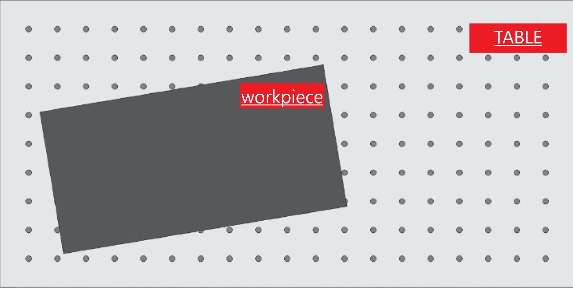
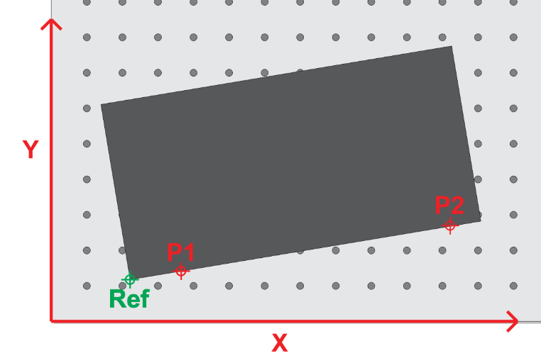
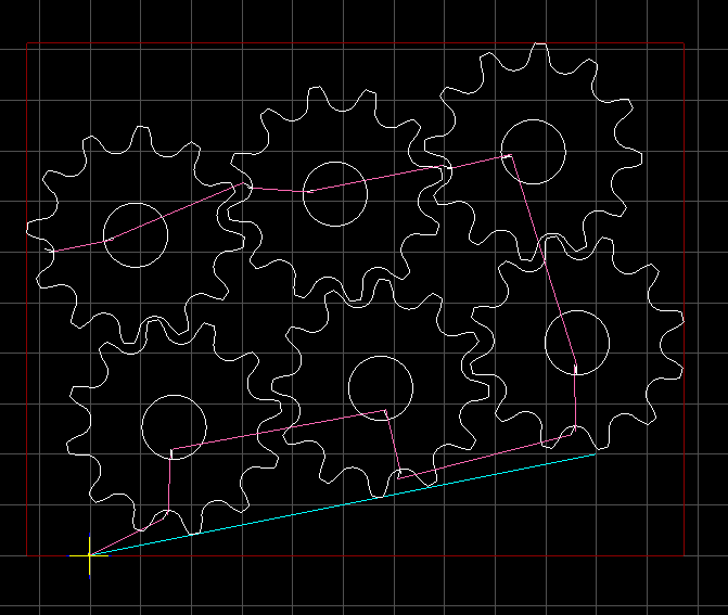
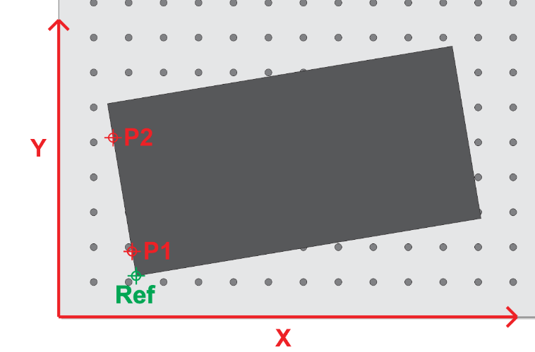
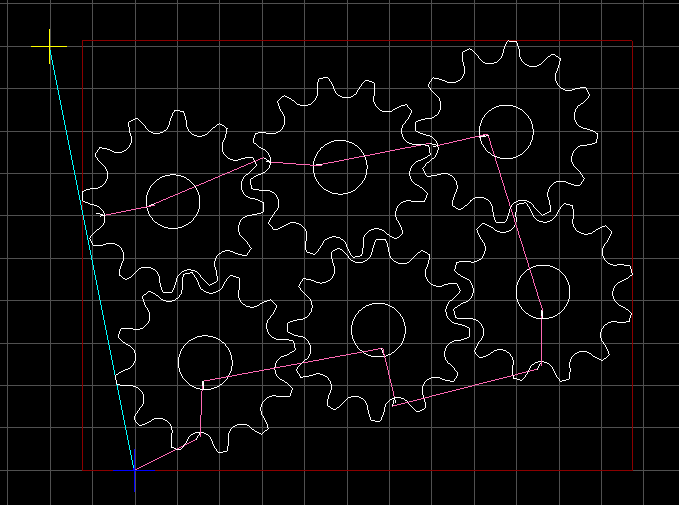
When placing the workpiece on the cutting table of the machine, there may be conditions that prevent aligning the piece with the motion axes (the workpiece may be placed askew or, in technical terms, not squared).
In these circumstances, it is necessary for the loaded design to rotate around the zero point according to how much the workpiece is skewed relative to the cutting table, so that the design aligns with the workpiece. To calculate the amount of rotation needed for the design, two points on the workpiece must be introduced to the software as shown below, allowing the software to compute the angle of rotation.
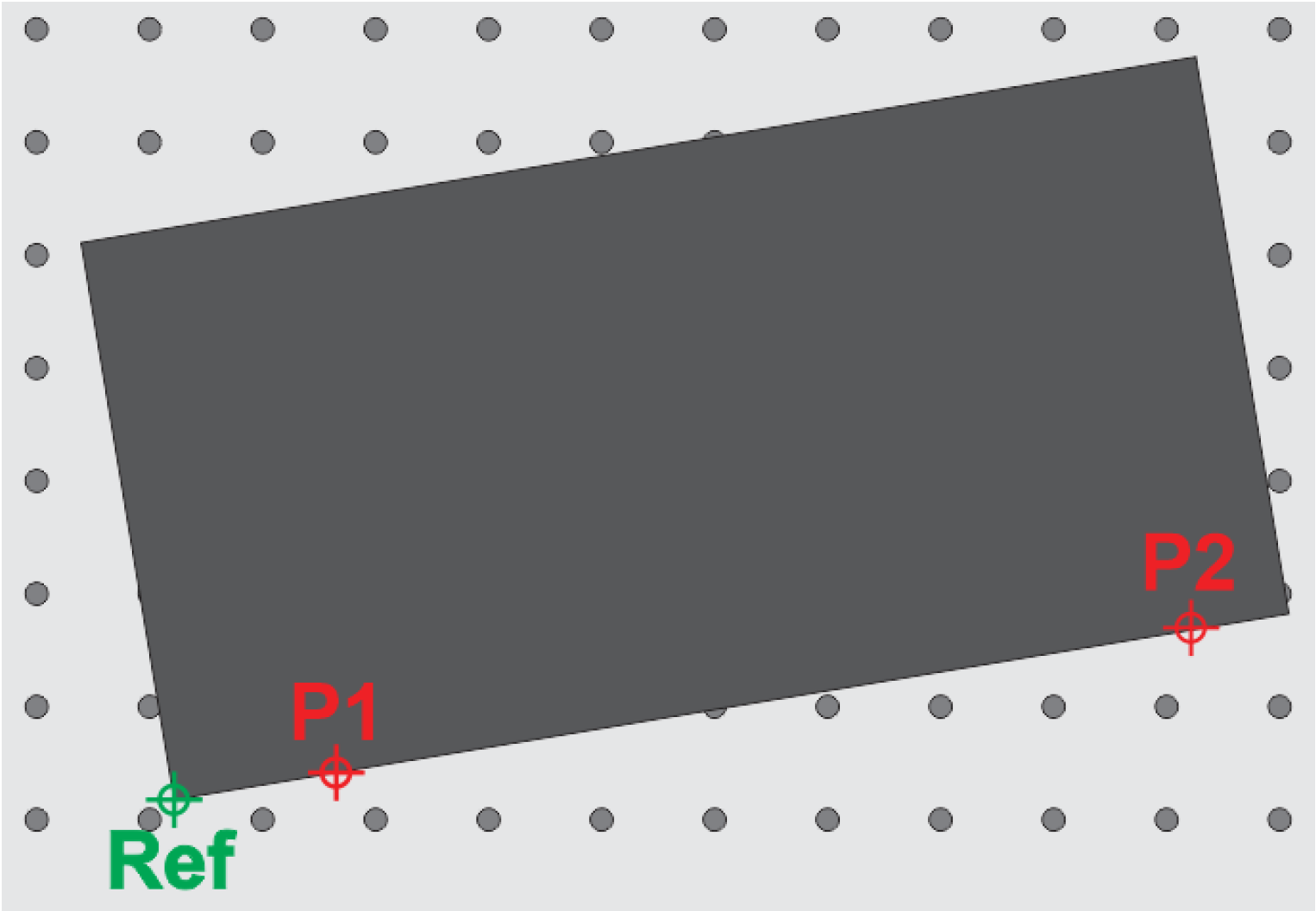
For this task, after loading the desired design, the cutting nozzle tip should be brought to a point tangent to the edge of the sheet. At the first point, press the P1 button, and at the second point, press the P2 button to introduce these two points to the software. By doing this, a blue line is drawn between these two points, which is exactly tangent to the edge of the workpiece.
After that, by pressing Sheet Align, the design becomes tangent to the blue line and is completely positioned within the workpiece.

It should be noted that the greater the distance between the two points P1 and P2, the more accurately this process will be performed. Now, we will have one of the following two scenarios:
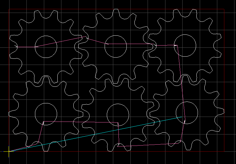
SheetAlignBaseAxis=X: In this scenario, the points are selected along the X-axis, and the loaded design will align with the line connecting the two points P1 and P2 (as illustrated below):
SheetAlignBaseAxis=Y: In this scenario, the points are selected along the Y-axis, and the loaded design will align with the line connecting the two points P1 and P2 (as illustrated below):
Calibration
Calibration Definition
Calibration refers to the process of aligning the motion value of an axis with one of the standard units or with a specific value. Common units in industrial devices are usually millimeters, centimeters, meters, inches, feet, degrees, etc., which are available for use based on the need. Therefore, the concept of calibration for the millimeter unit can be expressed as the alignment of the motion value of the desired axis with the millimeter unit. That is, in the case of measuring with measuring tools, the numerical value of the motion of the axis should be consistent with the measured value in millimeters.***
Motor Types in Calibration
In Radonix controllers, the calibration procedure for each axis is determined by the motor type. The key requirement for ensuring compatibility with various motor types is that the selected motor must support both pulse and direction signals.
Servo motors
A servo motor is a type of rotary actuator or linear actuator that allows for precise control of angular or linear position, velocity, and acceleration. It typically includes a motor coupled to a sensor for position feedback. Servo motors are essential in applications where precise positioning is required, such as in robotics, CNC machinery, and automated manufacturing. They use feedback signals to adjust motion parameters and can be controlled through servo mechanisms that utilize error-sensing feedback to correct performance.
Electronic Gear box:
An Electronic Gear Box is an integral component in modern servo systems, especially in applications that involve servo motors, like those used in automation and robotics. This technology essentially functions as a virtual gearbox that adjusts the speed and torque of a motor electronically, rather than mechanically. By manipulating the frequency and amplitude of the motor’s input signals, an electronic gearbox can change the output characteristics of the motor to suit specific tasks without needing physical gear changes.
Next step is essential for this subject is : Encoder Resolution
Encoder Resolution is a fundamental specification of servo motors, indicating the number of pulses an encoder emits for each complete revolution of the motor's shaft. This specification, expressed in pulses per revolution (PPR), is crucial for defining the precision with which the motor's position, speed, and acceleration can be controlled.
For instance, the Delta servo motor's B2 model features an encoder resolution of 160,000 pulses per revolution. This means that for every full turn of the motor shaft, the encoder generates 160,000 distinct signals. In contrast, the A2 model from the same brand boasts a much higher resolution of 1,280,000 pulses per revolution. This higher resolution allows for even finer control and more precise adjustments, which is essential in applications requiring meticulous positioning and detailed motion control.
High-resolution encoders are particularly beneficial in fields like robotics, CNC machinery, and automated assembly lines, where exact movements are paramount. The greater the encoder resolution, the smaller the movement that can be detected and controlled, enhancing the system’s accuracy and the quality of the output. This capability is crucial for optimizing the performance of high-precision tasks, ensuring that each component operates within tight tolerances and adheres to strict quality standards.
Understanding and setting the encoder resolution appropriately is a critical first step in the calibration of automated systems. It ensures that the machine operates smoothly and that each part produced meets precise specifications, thereby reducing errors and increasing overall efficiency in manufacturing processes. This detailed control over motor movements is what makes modern automated systems capable of performing complex tasks with high reliability and accuracy.
General Guide to Setting the Electronic Gear Ratio (E.G.) in Servo Drives
Overview
Configuring the Electronic Gear Ratio (E.G.) for servo drives is crucial for optimizing their performance in applications requiring precise motion control. This guide provides a generic approach to setting E.G. in servo drives, using the Delta B2 servo drive as a specific example to illustrate the process.
Requirements
- Servo drive with an integrated encoder
- Controller capable of generating pulse signals (e.g., a CNC controller)
- Technical specifications for both servo drive and controller
Step-by-Step Configuration
Step 1: Understand Encoder Resolution
- Objective: Recognize the encoder resolution, which is the number of pulses needed for one complete rotation of the servo motor's shaft.
- General Info: Encoder resolution is specified in pulses per revolution (PPR). It determines the precision with which the servo drive can control the motor position.
Step 2: Calculate Motor Speed in Rounds Per Second
- Objective: Convert the desired motor speed from RPM (revolutions per minute) to RPS (revolutions per second) to match the controller's output frequency.
- Procedure:
Formula: RPS=RPM/60
This calculation adjusts the time base from minutes to seconds, facilitating synchronization with pulse output.
Step 3: Determine Required Pulses Per Second
- Objective: Calculate the total pulses per second required based on the RPS and encoder resolution.
- Procedure:
Objective: Calculate the total pulses per second required based on the RPS and encoder resolution.
Procedure:
Multiply the RPS by the encoder resolution to get the required pulses per second.
Example Formula: Pulses per Second=RPS × Encoder Resolution
Pulses per Second=RPS ×Encoder Resolution
Step 4: Set the Electronic Gear Ratio (E.G.)
-
Objective: Adjust the electronic gearing to enable the controller's output to meet the servo motor's pulse requirements.
-
Procedure:

E.G.=Required Pulses / Controller’s Pulse Capability
Adjust the controller's settings to match the calculated E.G. ratio.
Example: Delta B2 Servo Drive
- Motor Speed: 3000 RPM
- Encoder Resolution: 160,000 PPR
- Controller's Pulse Capability: 500,000 pulses per second
- Calculation:
- Convert RPM to RPS: 3000 / 60 = 50
Required Pulses: 50×160,000 = 8,000,000
8,000,000 pulses per second=50×160,0008,000,000 , \text{pulses per second} = 50 \times 160,000
E.G.: E.G.=16=8,000,000 / 500,000
E.G.=16=8,000,000500,000\text{E.G.} = 16 = \frac{8,000,000}{500,000}
Set E.G. Ratio: 16:1
Testing and Validation
Objective: Ensure that the servo system functions correctly under the new settings.
Procedure:
Conduct a test run to check the accuracy and responsiveness of the servo drive.
Observe the motion to confirm that it aligns with expected parameters.
Additional Notes
Refer to specific servo drive manuals for detailed specifications and advanced settings.
Regular maintenance checks and recalibration are recommended to sustain optimal performance.
This comprehensive approach ensures that various types of servo drives can be efficiently integrated and operated in systems requiring high precision, such as in automation and robotics.
Stepper motors
A stepper motor is an electromechanical device that converts electrical pulses into discrete mechanical movements. It operates on the principle of electromagnetism, achieving precise movement and positioning by rotating in fixed step increments. This feature makes stepper motors ideal for applications requiring highly accurate and controlled movements such as 3D printers, CNC machines, and robotics. Stepper motors are favoured in systems that require simple, open-loop control for precise short-distance or limited-angle applications.
stepper motor drivers often include DIP (Dual In-line Package) switches that allow users to configure specific settings for motor operation. These switches are critical for adapting the stepper motor's performance to the needs of a particular application. Here's a breakdown of common settings that can be controlled via DIP switches on a stepper motor driver:
Common DIP Switch Settings on Stepper Motor Drivers:
Microstepping: Microstepping is a method of controlling stepper motors so they move in smaller increments. This results in smoother motion and higher resolution positioning. DIP switches allow for setting different microstepping configurations (e.g., full step, half step, quarter step, etc.).
Current Setting: To optimize performance and efficiency, the current output to the stepper motor can be adjusted using DIP switches. This helps match the current to the motor's specifications to prevent underperformance or overheating.
Decay Mode: Decay mode settings control how quickly the motor's current decreases in its off cycle. Proper decay mode settings can improve the performance and response time of the motor, especially at higher speeds or varying loads.
Torque Settings: Some drivers allow the torque output of the motor to be adjusted via DIP switches. This setting is crucial when different loads or pressures are expected on the motor during operation.
How to Use DIP Switches:
Refer to the Manual: Always check the stepper motor driver’s manual for specific instructions on what each DIP switch controls. This guide is essential for understanding how to correctly set the switches according to your needs.
Set Before Powering: It’s important to set the DIP switches when the driver is powered off to avoid damaging the motor or the driver.
Testing and Adjustment: After setting the DIP switches, run tests to ensure that the motor operates as expected under load. Adjust the settings if necessary to achieve the desired performance
Indeed, setting the DIP switches to the highest microstepping value available on the stepper motor driver is often recommended by experts to achieve the smoothest movement possible. This practice is especially prevalent in applications where precision and smoothness are critical, such as in high-precision machining, robotics, or medical equipment. Here’s a closer look at why this recommendation is prevalent and how to implement it effectively:
Why Set to Highest Microstepping Value?
- Increased Resolution and Smoothness:
- Higher microstepping values increase the number of steps the motor takes to complete one full revolution. This results in smaller step increments, which smooths out the motion, reducing vibrations and resonance that are more noticeable at lower microstepping settings.
- Reduced Mechanical Noise:
- Smaller step increments also contribute to quieter operation. The smoother transition between steps minimizes the noise produced by sudden movements in stepper motors, which is beneficial in noise-sensitive environments.
- Enhanced Positional Accuracy:
- Although microstepping increases resolution, it's important to note that it does not inherently increase the positional accuracy due to potential step errors accumulating over time. However, in practical applications, finer steps allow for more precise control over motor positioning, which can be crucial for delicate operations.
Calibration ways
In Radonix controller, each axis has the ability to calibrate separately, and even the axes can be calibrated in different units. The variable representing the calibration factor in this controller is the Step variable, which to access it, you need to open the Radonix software and after opening the Setting window, go to the System branch and then the Axis sub-branch represents the number between 1 to 6, which specifies the axis number.
Now based on this E.G calibration process can be feasible through two ways
1. Radonix CAM Calibrator and Measurement
In this calibration method, the basis is measurement with measurement tools and equipment. Therefore, the accuracy of the measuring tool, measurement accuracy, and mechanical errors of the device directly affect the quality of calibration. Although this method is not as precise as computational methods, it is a widely used method due to the lack of information on motors, gearboxes, pulleys, and gear wheels, whichare sometimes not available. The basis of this method is measuring the displacement value for a specific number of pulses.To facilitate, improve accuracy, and speed up calibration using the measurement method, Radonix has provided a free software called CAM-Pro Calibrator, which is automatically installed with the main Radonix software. Based on the physical displacement measurement of the axis and the required number of pulses for this displacement, the software calculates the step value.
Since pulse counting in this method is the responsibility of the controller, there is no error in pulse measurement. Therefore, the measurement accuracy in this method is directly related to the physical measurement accuracy. In addition, the greater the distance between the two measured points, the larger the pulse value will be, which means the denominator will increase, and according to the constant error, the overall step value obtained will be more accurate. Therefore, calibrating based on two points will result in more accurate results.
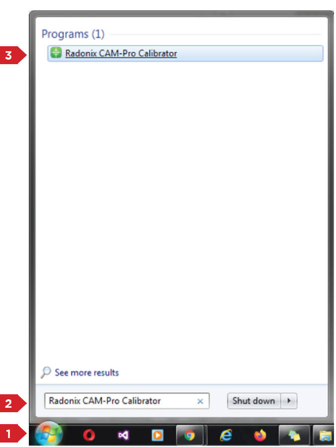
Introduction to CAM-Pro CalibratorAs explained in the previous section, the CAM-Pro Calibrator software is installed along with the CAMPro software. There are two ways to find the Calibrator software after installation. According to the first method, simply go to the installation location of the software, which is usually in the C drive of Windows by default, then go to the (x86) Program Files folder, open the Radonix folder, and the CAMProCalibrator software is visible in the Radonix CAM-Pro file. According to the second method, simply go to the Start menu and search for Radonix CAM-Pro Calibrator in the Search option.
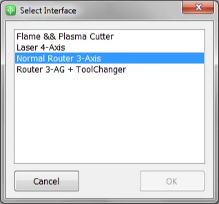
This program consists of two windows. The first window only appears if there are multiple active interfaces on a computer (Figure 3). Through this window, you can select the desired interface and launch it by pressing the 'Ok' button. If there is only one active interface on the computer, the interface selection window will not open, and the main window will open directly.
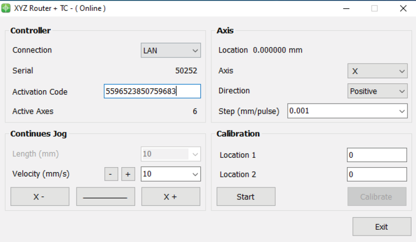
When you open the CAM-Pro Calibrator software, you will see Figure (4), which components are as follows:
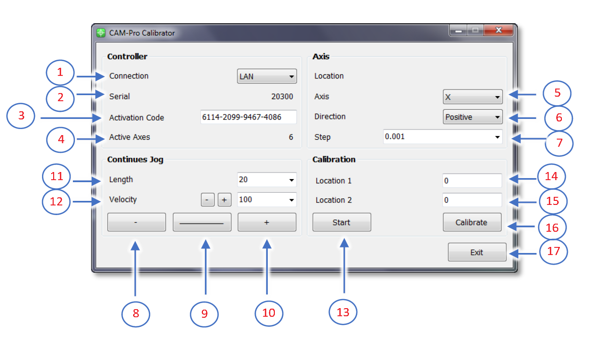
- Connection:
- ProLan controllers must be set to LAN mode.
- ProUSB controllers must be set to USB mode.
- Serial:
- Displays the controller's serial number.
- Activation Code:
- Displays the 16-digit code used to activate axes.
- Active Axes:
- Shows the number of activated axes using the activation code.
Axis Section
5.Axis:
- Allows selecting the desired axis for calibration.
6.Direction:
- Select the appropriate movement direction for standard axes:
- Negative: Movement towards the negative direction.
- Positive: Movement towards the positive direction.
7.Step:
- Sets the step size for calibration or output pulses. After calibration, the step is automatically recorded in the settings.
Continuous Jog Section
8.Negative Jog:
- Enables manual movement in the negative axis direction.
9.Jog Mode:
- Allows selecting the jog movement type:
- Continuous: Smooth, uninterrupted movement.
- Incremental: Moves in defined steps.
10.Positive Jog:
- Enables manual movement in the positive axis direction.
11.Length:
- Defines the incremental movement distance when the Incremental mode is active.
Velocity Section
12.Velocity:
- Used to set the speed for manual movements.
- The positive and negative buttons next to the Velocity option increase or decrease the speed of manual movements.
Calibration Section
13.Start:
- Button to initiate the calibration process.
14.Location 1:
- Used to set the initial position for calibration.
- This position must be relative to a fixed point on the measured axis.
15.Location 2:
- Used to set the final position for calibration.
- This position must also be relative to a fixed point on the measured axis.
16.Calibrate:
- Button to complete the calibration process and calculate the calibration factor.
17.Exit:
- Button to exit the calibration program.
Summary for calibration software, follow these steps:
First, select the desired axis from the Axis section for calibration. Then, by selecting a low speed and moving the axis, ensure the direction of movement is correct. If the movement direction is incorrect, choose the appropriate direction using the Direction section. Next, move the axis to one of the two ends of its travel range. Since the starting direction in this method is not important, it does not matter which end of the axis is chosen as the starting point. Once the axis is in the correct position, measure a point on the axis relative to a fixed point on the machine using an appropriate measuring tool, record this at Location 1, and press the Start button. Note that unit selection is entirely optional, so if calibration with a specific unit is required, all measurements should be based on that unit. For example, the device can be calibrated in units of inches, meters, centimeters, millimeters, or even micrometers.
Move the axis to the opposite end. If measurements at greater distances are possible and the measuring tool is sufficiently accurate, measurements over longer distances will yield more precise results. After moving the axis to the second point, measure this point similar to the first relative to the fixed point on the machine, record this at Location 2, and then press the Calibrate button. Using these measurements, the calibration step or factor is calculated and automatically registered in the designated interface. The calibration process can be repeated as many times as needed for each axis.
Please note that if the activation code has not been entered, an error message will be displayed when opening the CAM-Pro Calibrator software.
2. Mathematics Calculation
Computational MethodTo align the axis movement with the desired unit, a calibration coefficient called "Step" is used. To access this variable, first open the software and then navigate to the Setting window, proceed to the System branch, and the sub-branch Axis (where represents a number between 1 and 6, indicating the axis number). The Step variable is located within these sub-branches, and each axis has its own specific Step variable.
If the unit of axis movement is in millimeters, the unit of this variable will be millimeters per pulse. If the movement unit is centimeters, inches, or any other unit, the Step variable will also be expressed in that unit per pulse. Essentially, this represents the amount of movement of the desired axis per one pulse transmitted to that axis's motor driver. Therefore, to calculate this variable, one must understand the relationship between the motor's movement amount per input pulse to the driver and the conversion ratios of gearboxes, pulleys, and any other type of motion transmission. For a better understanding of these calculations, consider the following examples:
**Example 1:**Consider a linear axis of a CNC machine where the measurement unit is in millimeters, and it is equipped with Panasonic A5 motors that have a 10:1 gearbox ratio. This motor is connected via a pinion with an effective diameter of 66 millimeters to a rack. Now, calculate the Step value for the specified axis.
Please note that each piece of information plays a crucial role in these calculations and can be used to compute the step size of the axis for calibration purposes. For example, knowing the type of motor driver and its specifications determines the relationship between the input pulse to the driver and the resulting movement of the motor shaft.
In Panasonic A5 motors, at a rate of 500,000 pulses per second, the motor reaches a speed of 3000 rpm. In the first step, we calculate the motor's rotational speed per second. Here, the figure 3000 represents the number of motor revolutions per minute, which we convert to seconds by dividing by 60, the number equivalent to one minute. The result is 50, meaning the motor makes 50 rotations per second. Therefore, the equation can be written as: Motor rotational speed per second = 3000 rpm / 60 s = 50 r/s. In the second step, we need to calculate the amount of axis movement per one rotation of the motor.
In fact, in this example, the distance traveled will be equal to the circumference of a circle, and the circumference of a circle is calculated as the diameter of the circle multiplied by π (pi) Or approximately 3.1415 meters. As mentioned in Example 1, a pinion with a diameter of 66 millimeters and a 10:1 gearbox are used in the mechanics, so we will have The amount of axis movement per one revolution of the motor is calculated as (1/10) * 66(mm) * 3.1415 = 20.7339 mm The result obtained is the amount of axis movement per one rotation.
The final step is to write the ultimate equation and find the unknown value, which in this case is the Step variable. As observed, all calculations are based on 500,000 pulses sent by the controller and a motor speed of 3000 rpm. Therefore, to calculate the movement or distance traveled per 1 pulse, the result obtained needs to be divided by 500,000. However, as stated earlier, this motor makes 50 revolutions per second. Thus, it is important to note that while the amount of movement was calculated per 1 revolution in the second step, the motor completes 50 revolutions per second. Therefore, the number obtained in the second step must be multiplied by 50 to find the total distance traveled per second by the motor. Now, we will rewrite the overall equation once more.
Step(mm/pulse) = 50(r/s)∗20.7339(mm) / 500000(pulse/s) = 0.00207339 (pulse/mm)
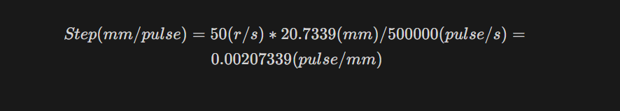
From this equation, the Step value is calculated. This value means that the motor moves 0.0207339 millimeters per 1 pulse received.
Please note that the computational method used in Example 1 is intended for the calibration of linear axes.
Step(unit/pulse) = The value of the axis movement per one rotation of the motor * the number of motor rotations per second / Number of pulses sent by the controller per second
Example 2: Consider a rotary axis of a CNC machine where the measurement unit is in degrees. It is equipped with Panasonic A5 motors, which have a 25:1 gearbox connected to a 12-tooth pulley. This pulley is then linked via a belt to a 44-tooth pulley. Now, calculate the Step value for the specified axis.
Motor rotational speed per second = 3000 rpm / 60 s = 50 r/s.
In the final step, we must multiply the effective values, such as the gearbox ratio, the pulley ratio, and the motor's rotational speed per second, by 360. As we observed, all calculations are based on 500,000 pulses sent by the controller and a motor speed of 3000 rpm. Therefore, to calculate the movement per 1 pulse, we must divide the obtained value by 500,000. This simple estimation will yield the Step value.
Step= 50(r/s)∗(1/25)∗(12/44)∗360 / 500000(pulse/s) = 0.000392727272
From this equation, the Step value is calculated.
The general equation for calibrating rotary axes is as follows:Step(unit/pulse) = Rotation amount per second in the motor * effective value * 360 * / Number of pulses sent by the controller per second
Please note that whether calculating linear axes or rotary axes, the more significant digits we use, the more precise the calculation results will be.
Please note Pulse divisions in stepper motors directly impact these calculations. For simplicity, one can first calculate the motor rotation for a specific pulse value and then incorporate the result into the equations above.
Please Note In drives where the number of pulses required to reach the maximum motor speed exceeds the number of pulses produced by the controller, one can achieve the maximum motor speed by increasing the electronic drive ratio to a specific extent. For example, if a drive requires 4 million pulses per second to reach the maximum motor speed, and considering that Radonix produces 500,000 pulses per second, an electronic drive ratio of 8 should be considered to achieve the maximum rotational speed of the motor.
After opening any DXF file, the DXF Reader window automatically opens and displays the components contained in the file.
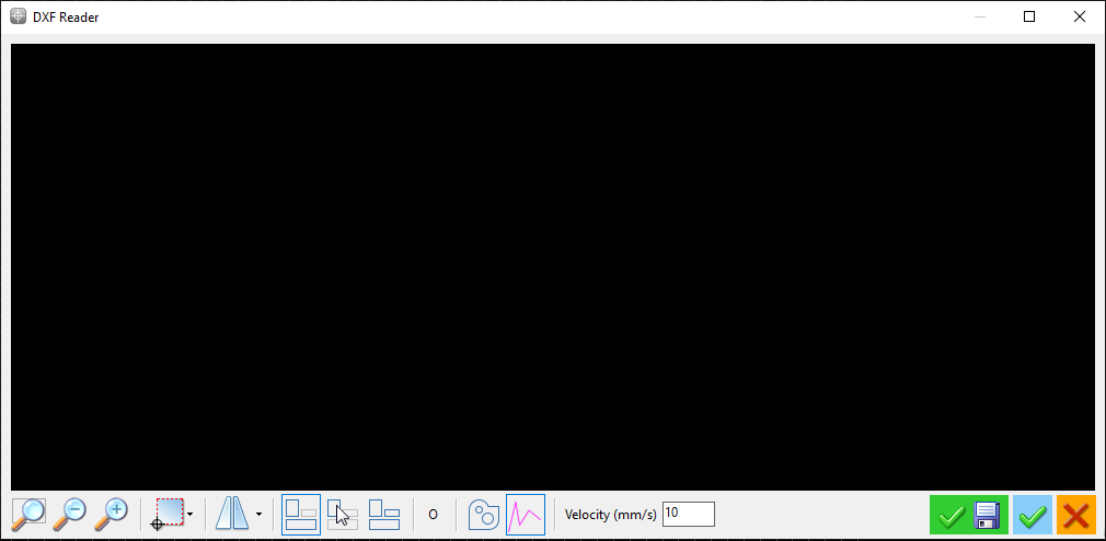
The toolbar below this window includes the following items:

The Zoom Fit button, which when clicked, displays the opened design fully within the DXF Reader window.

The Zoom Out button, which when clicked, reduces the scale of the opened design by one level. Additionally, you can perform the Zoom Out action by holding the mouse pointer over the design and scrolling the Mouse Wheel upwards.

By clicking on this option, the opened design enlarges by one level. Additionally, you can perform the Zoom In action by holding the mouse pointer over the design and scrolling the Mouse Wheel downwards.

This option is used to determine the position of the Reference point or zero of the workpiece in the opened design, which includes the following items:
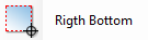
This option considers the bottom right corner of the shape, or in other words, the endpoint in the positive direction of the X-axis and the endpoint in the negative direction of the Y-axis, as the zero point.

This option considers the top right corner of the shape, or in other words, the endpoint in the positive direction of the X-axis and the endpoint in the positive direction of the Y-axis, as the zero point.

This option considers the top left corner of the shape, or in other words, the endpoint in the negative direction of the X-axis and the endpoint in the positive direction of the Y-axis, as the zero point.
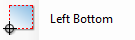
This option considers the top left corner of the shape, or in other words, the endpoint in the negative direction of the X-axis and the endpoint in the positive direction of the Y-axis, as the zero point.
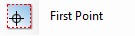
This option considers the starting point of the first piece in the opened design as the zero point.

This option is used for applying rotation (Rotate) or mirroring (Flip) to the design, which includes the following items:

90-degree rotation clockwise.

90-degree rotation counterclockwise.

Mirror across the X-axis
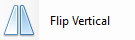
Mirror across the Y-axis.
In any design file, by default, parts are cut in the same sequence as they are drawn in the design software, and the start and end points of each cut are chosen based on the direction of the line drawn in the design software. However, in the DXF Reader section, the order and direction of the part cuts can be changed as desired. When you open a DXF file, by default, all parts are active for execution and the cutting direction is specified.

By clicking on the 'Arrange Objects' option, all parts are deactivated. By left-clicking on any part, it becomes activated for cutting, and by clicking again, it is deactivated. Additionally, by right-clicking on parts, you can reverse the cutting direction. If we have selected a number of parts for which the order of execution is important .for selecting the rest of the parts for which the order of execution does not matter from Select objects


The 'Default Arrange' option is for executing the design in the default order set by the design software. The 'Optimize' option selects the order of part cuts in such a way that minimizes the execution time of the file (the order of cuts is arranged such that after finishing the cut of one part, the closest starting point to the endpoint of the previous part is chosen).

Clicking on this option selects only the parts that are in Polyline form for cutting, and deactivates the parts that do not have this feature.

The pink lines displayed in the figure are non-cutting or Traverse lines, which indicate the path of the machine's movement when transitioning between two different pieces. Clicking on this option allows you to activate or deactivate the display of these lines.
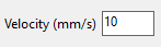
This section determines the cutting speed of the parts, and the unit is millimeters per second. Note that this speed only specifies the machine's movement speed during cutting and does not affect the machine's travel speed between two different pieces within a design.

After completing modifications on the loaded file, by clicking on this option, while preserving the original file, you can save your changes before executing the file to avoid the need for re-editing the design in future runs. It should be noted that the file is saved with a .CNC extension as a G-Code file, and it cannot be edited in subsequent runs.

By clicking on this option, without saving changes, the DXF Reader window will close, and the design will be loaded and ready for execution.

By clicking on this option, the DXF Reader window will close without loading the design.
Tips on setting up different cutting machines:
CNC Oxy-Fuel Cutting Machine: In oxy-fuel cutting machines with an automatic ignition system, separate solenoid valves on the gas output, pre-heated air, and oxygen for cutting, the outputs are defined as follows: ➢ C-PreCutPin: Automatic ignition
➢ C-PreCutPin+CutPin: Solenoid valve for gas output and solenoid valve for pre-heated air output
➢ C-CutPin: Solenoid valve for oxygen cutting or jet
The PreCutTime parameter can be used to control the duration of molten pool formation.
The CutTime parameter can be used to control the duration it takes to pierce the workpiece.
Considering that the outputs of the control board supply a maximum current of 200 milliamps to the consumer and drawing more current than this amount can damage the output, even if using a 24-volt solenoid valve, avoid directly connecting the solenoid valve to the control board and always use a relay.
In machines where the distance from the solenoid valves to the cutting nozzle is significant and the length of the intermediary hose is long, to prevent damage to the end part of the cut, be sure to use the PostCutTime parameter. This ensures that the machine pauses until the gas in the hoses is fully discharged, preventing damage to the workpiece.
A significant part of the cutting quality in CNC oxy-fuel cutting machines depends on the operator's skill in adjusting the flame and the distance of the cutting nozzle to the workpiece.
Need Assistance or Have Feedback?
Thank you for choosing Radonix. Your satisfaction is our priority, and we are here to assist you with any questions, additional information, or feedback regarding our products and services.Feel free to contact us through the details below:
📍 Address:HALİL RIFAT PAŞA MAH. YÜZER HAVUZ SK. PERPA TİC MER B BLOK NO: 1 /1 İÇ KAPI NO: 1689, ŞİŞLİ/İSTANBUL, TURKEY
📞 Phone:+90 212 222 9522 +90 553 920 5500
📧 Email:English Support: [email protected] Turkish Support: [email protected]
🌐 Website:radonix.com | radonix.com.tr We appreciate your feedback and look forward to assisting you!