Smart 3AS
How to Wire PC-Smart 3AS Series Controllers to Various Servo Brands
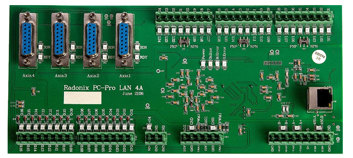
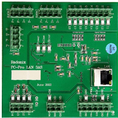
The 3AS series controllers—also known as step motor controllers—can be connected to and drive servo drivers (such as the 2A, 4A, and 6A series). The two models differ mainly in:
- Maximum output pulse frequency per axis
- How each axis is wired to the controller
Both topics are explained in detail below.
- Servo series max PWM per axis: 500 kHz
- Step series max PWM per axis: 40 kHz
Since the servo series’ maximum pulse frequency is 12.5 × that of the step series, if you substitute a step-series controller for a servo-series controller, you must increase the electronic “gear ratio” in the servo drive by a factor of 12.5. For example, with Delta B2-series 3,000 rpm servos:
- If you calculate a 16:1 electronic gearbox ratio, in “steering controller” mode you’d set
12.5 – 200 * 16.
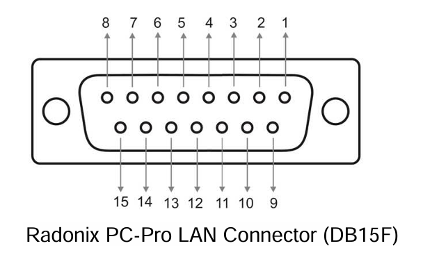
This calculation method applies to all servo brands. The DB15-F connector on the step-series controller carries all pins for sending pulses/direction and for feedback. In the servo series, only four pins (Pulse±, Dir±) go to each axis; the rest are wired to +24 V, GND, or I/O on the controller. Below is each servo-series pin’s function, and how it maps on Styria-series drives—so you can wire any servo brand to Radonix 3AS controllers.
-
Pin 1: +24 V
- Servo drives expect a +24 V feed (COM) to enable their digital inputs. On servo-series controllers this is Pin 1.
- On step-series controllers, wire Pin 1 directly to +24 V on your power supply or controller.
-
Pin 2: Dir –
- On servo drives, connect this to the drive’s “D–” input.
-
Pin 3: Dir +
- On servo drives, connect this to the drive’s “D+” input.
-
Pin 4: P –
- On servo drives, connect to “P–”.
-
Pin 5: P +
- On servo drives, connect to “P+”.
-
Pin 6: Servo ON
- On step-series controllers, map this to one of the digital outputs (O.1–O.4) and in software name it ControlStatusPin. When the software is online, it will assert this output.
- You may also tie all Servo ON pins to +24 V or skip them entirely by changing drive parameters—freeing up an output.
-
Pin 7: Servo Ready
- Many servo drives have DO+ / DO– feedback. Wire DO– to GND and DO+ to one of the controller’s digital inputs (I.1–I.8), then in software set it as Emergency, NC=True.
- If you’re short on inputs, you can OR all DO+ lines together into one input.
-
Pin 8: Encoder Zero
- Optional; leave unconnected unless needed.
-
Pin 9: Alarm Reset
- Wire to one of O.1–O.4 and name it ClearAlarmPin in software.
- You can also add a “Clear Alarm” button in the UI, linked to ClearAlarm, to reset all drives.
10–15. Pins 10–15: GND
- These are the “Limit” and “Emergency” inputs on many drives, normally closed. If left floating, they trigger alarms. You can:
- Set them to Normally Open or disable them in software.
- Tie them all to GND to suppress alarms.
- Wire them to actual limit switches or sensors.
Summary Table
Pin | Function | Step-Series Label |
|---|---|---|
1 | +24 V |
|
2 | Dir – | D – |
3 | Dir + | D + |
4 | Pulse – | P – |
5 | Pulse + | P + |
6 | Servo On | O.1–O.4 |
7 | Ready | I.1–I.8 |
8 | Encoder Zero | Not connected |
9 | Alarm Reset | O.1–O.4 |
10 | GND | GND |
… | … | … |
15 | GND | GND |
Example: Delta ASDA-B2
Step-Series Label | Description | ASDA-B2 Pin |
|---|---|---|
| +24 V | 11 |
D – | Dir – | 37 |
D + | Dir + | 39 |
P – | Pulse – | 41 |
P + | Pulse + | 43 |
O.1–O.4 | Servo On | 9 |
I.1–I.8 | Ready (DO+) | 7 |
Not connected | Encoder Zero | 44 |
O.1–O.4 | Alarm Reset | 33 |
GND | CW Limit | 32 |
GND | CCW Limit | 31 |
GND | Emergency | 30 |
GND | Ready (DO–) | 6 |