Step-by-Step Guide
Introduction
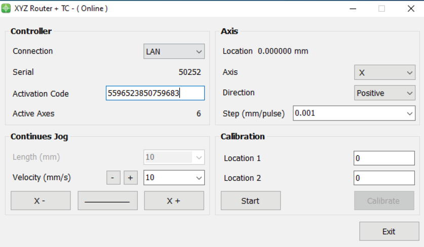
The XYZ Router -TC interface serves as a user interface between the operator and advanced software for a three-axis CNC machine, featuring capabilities such as automatic tool change, support for various types of linear and rotary parking systems, and digital output control during G-code execution via M-Code. Complementary features like the ability to connect an XBOX controller and keyboard as remote controllers, automatic park position adjustment, and the definition of up to 6 reference points for work start positions make machine operation easy and precise for operators. All inputs and outputs are pre-configured by default, so no additional programming is required. The interface can also be customized visually to fit the industrial needs and branding of manufacturing companies.
One of the key advantages of Radonix software and interfaces is the ability to install, set up, and display G-code in 3D while performing various settings such as defining digital inputs and outputs, adjusting speed, acceleration, and other related parameters. These settings can even be tested and simulated in G-code mode without requiring hardware. This feature allows users to gain an initial understanding of Radonix controllers’ performance and functionality, significantly simplifying the setup and configuration process.
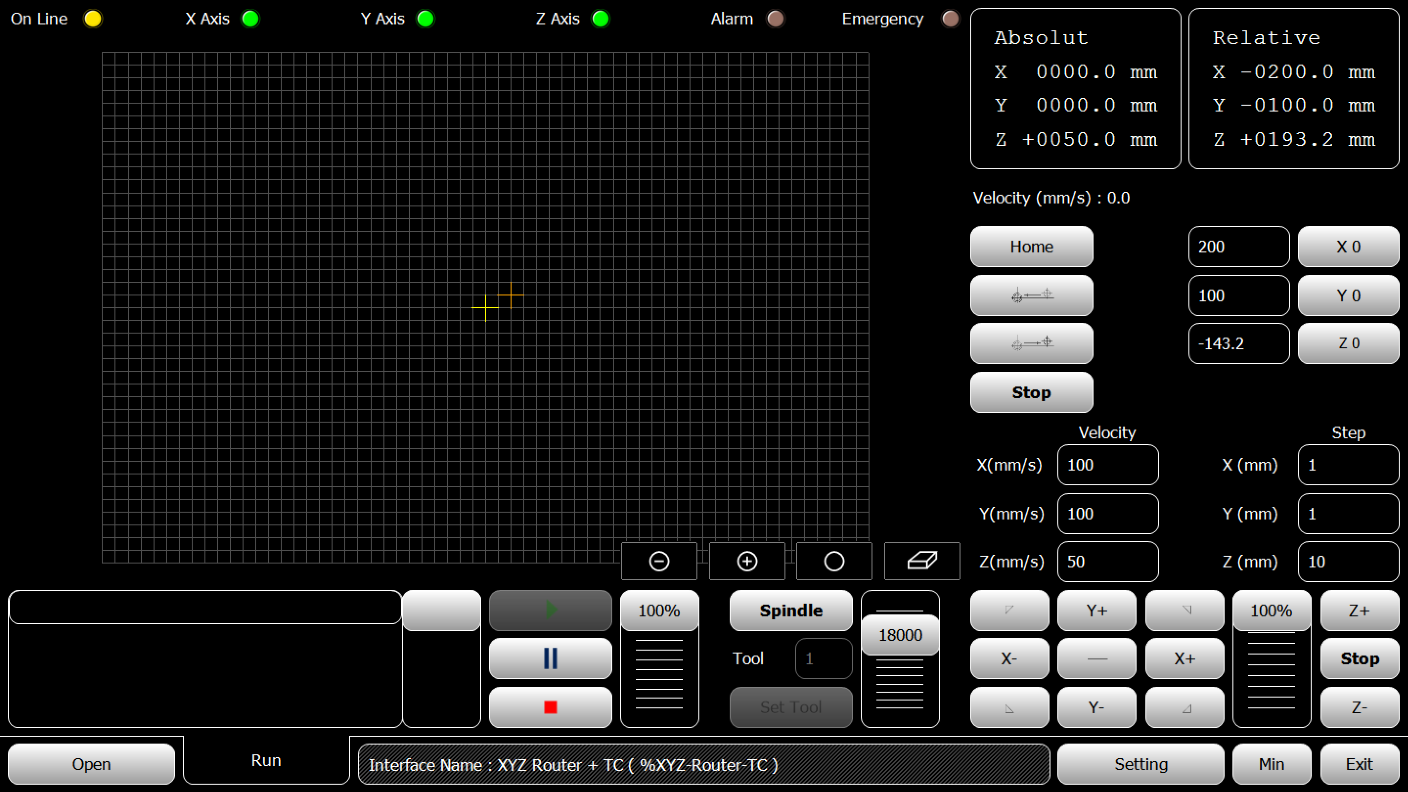
This interface is called XYZ Router +TC
For starting primary installation there are some steps to go through it and has a successful installing
Interface workspace
1- Study about different part of interface which is named and indicated in photo it means that you should get familiar with all elements like Buttons , screen , bars , volume , values , … anything on interface you have accesses
Get Start
Workspace Descriptions
Here's a detailed description of each section and button on this CNC controller interface
Top Status Bar

- Online (Yellow Light): Indicates the machine's connection status. If the controller and software are connected, it is on.If there is no communication between the controller and the software, it will be turned off or displayed in gray color.
- X Axis, Y Axis, ZAxis (Green Lights): These lights show the operational status of each axis. Green typically means these axes are active or ready.(FAQ)
- Alarm, Emergency (Brown Lights): Indicators for critical safety statuses. When activated, they may change color (e.g., red) to signal an alarm, emergency stop.(FAQ)
Position and Speed Readouts (Right Panel)
- Absolute Position (Top Right Box):
Absolute: Displays the coordinates of the axes in reference to thehome point.(FAQ)
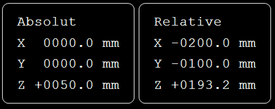
- Relative Position (Besides Absolute Position):
Relative : Shows the coordinates of the axes relative to the reference point.
- Velocity (Below Relative Position): Shows the current operational speed in mm/s, useful for monitoring real-time cutting or movement speeds.(FAQ)

Position Controls (Mid Right Panel)
- Home (Target Icon): Moves the machine to its home or origin position.

- X0 , Y0 , Z0 (Crosshair Icons): These buttons take spindle to the X , Y , Z coordinates to zero or move the tool to the zero point in each axis.(FAQ)
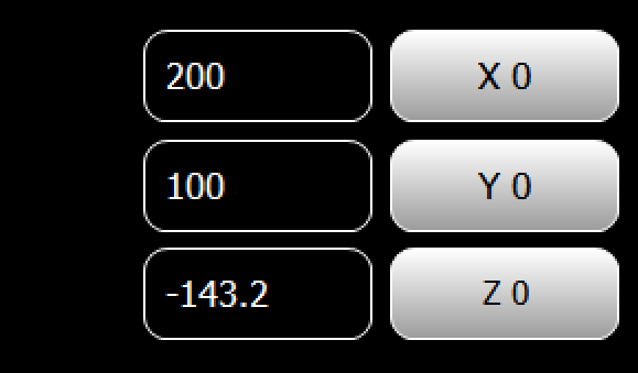
-
You have two options for saving reference points. The first option is to manually move the tool by jogging, and when you reach the desired point, press the corresponding button to save that position for the axis. The second option is to directly enter the precise position value in the input box in front of each button.
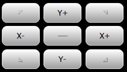
Manual Jogging Controls:
- Arrows (X+, X-, Y+, Y-): These buttons manually jog the machine along the X and Y axes, allowing for precise positioning adjustments by moving the tool head incrementally.
You can switch the jog mode by pressing this button according fig 01-05 and it will change to figure 01-06, changing from continuous to incremental movement. This means you can define a value in this section according fig 01-07 which has been indicated in red area , and after pressing the coordinate axis jog, the axis will move by the amount you have entered.
—————————————————————————————————


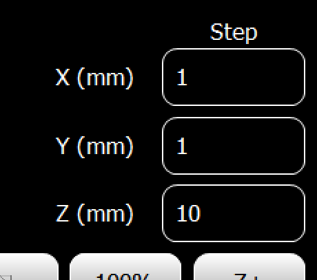
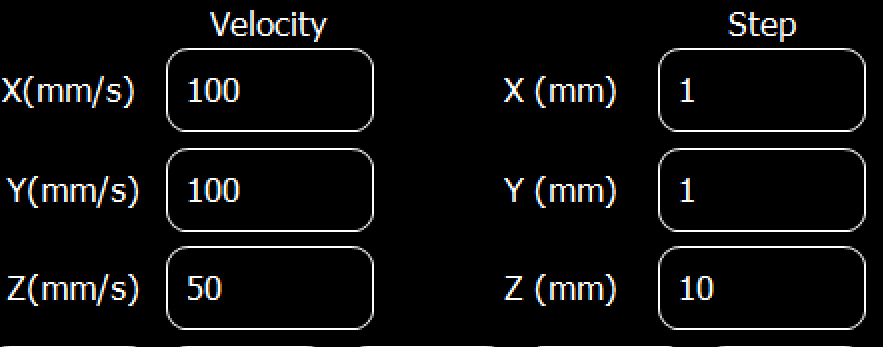
Feed Rate and Tool Parameters (Lower Right Panel)
- V (mm/s) and Step**(mm)**: Input fields for setting feed rates and movement limits along each axis. "V" controls the velocity (or speed) in mm/s, and "L" could define the step size for each manual jog.
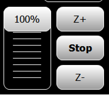
- Scroll (Vertical Slider on Bottom Right ):According to figure 01-08 which is demarcated with red area or Allows for real-time adjustment of the feed rate or speed as a percentage. This control can quickly change the speed without directly altering program values.
Main Program Controls
- Settings (Gear Icon): Opens the configuration menu, where detailed settings for the CNC machine can be adjusted.

- The Exit icon allows you to close the program
- The Minus icon lets you minimize it.
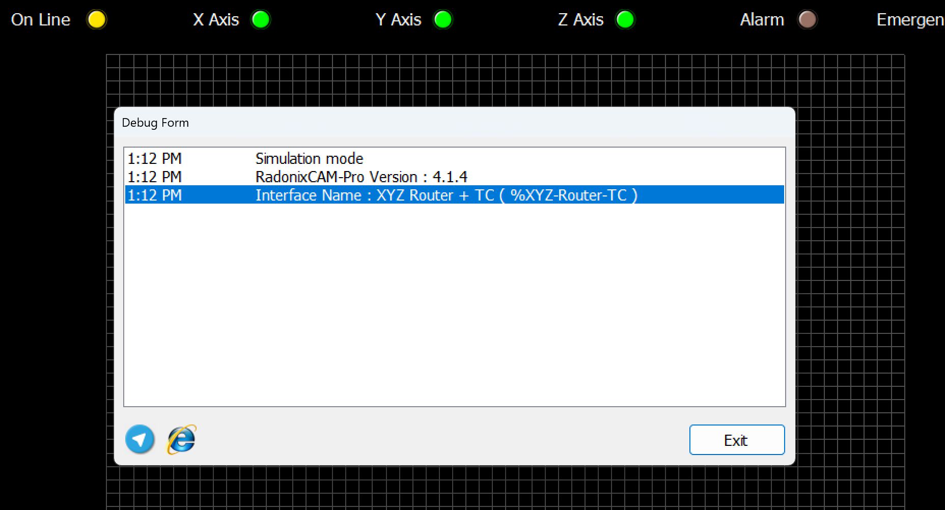
Interface specification :

This section of the interface displays the current status and features of the system. It also updates to show alarms and processes every second. For a detailed report, double-click on this section.
Main Program Controls (Bottom Center)
- Open File (Folder Icon): Opens a file dialog for loading a CAM (Computer-Aided Manufacturing) file, typically a G-code or DXF program.
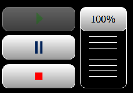
This section is dedicated to controlling G-Code execution:
- RUN: This button starts the G-Code process.
- Pause: This button halts the toolpath.
- Reset: This button resets the toolpath.
Spindle Button and Scroll Rotation Control
-
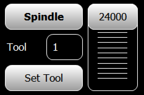
Spindle Button:
The spindle button allows the operator to manually control the spindle, enabling it to be turned on or off as needed. This provides flexibility for tasks that require direct manual control of the spindle’s operation.
-
Spindle Rotation Control:
The spindle rotation speed can be adjusted using the scroll control. By rotating the scroll, the operator can precisely set the spindle’s rotational speed, ensuring optimal performance for specific cutting or machining tasks.
Tool Management in TC-Enabled Interfaces
In CNC interfaces with the Tool Change (TC) option, such as the XYZ Router + TC, the following features are provided:
-
Tool Number:
The interface allows the operator to select and display the desired tool number. This ensures the correct tool is used for the operation.
-
Set Tool:
The Set Tool button issues an order to take the selected tool to the Tool Height Sensor. This process automatically measures the tool height, ensuring accurate calibration and alignment of the tool with the workpiece.
Display and Zoom Controls (Center of Main Display)
- Grid Display (Black Area with Grid): Shows the work area and toolpath visualization. The grid assists in visualizing the relative position of the tool and workpiece.
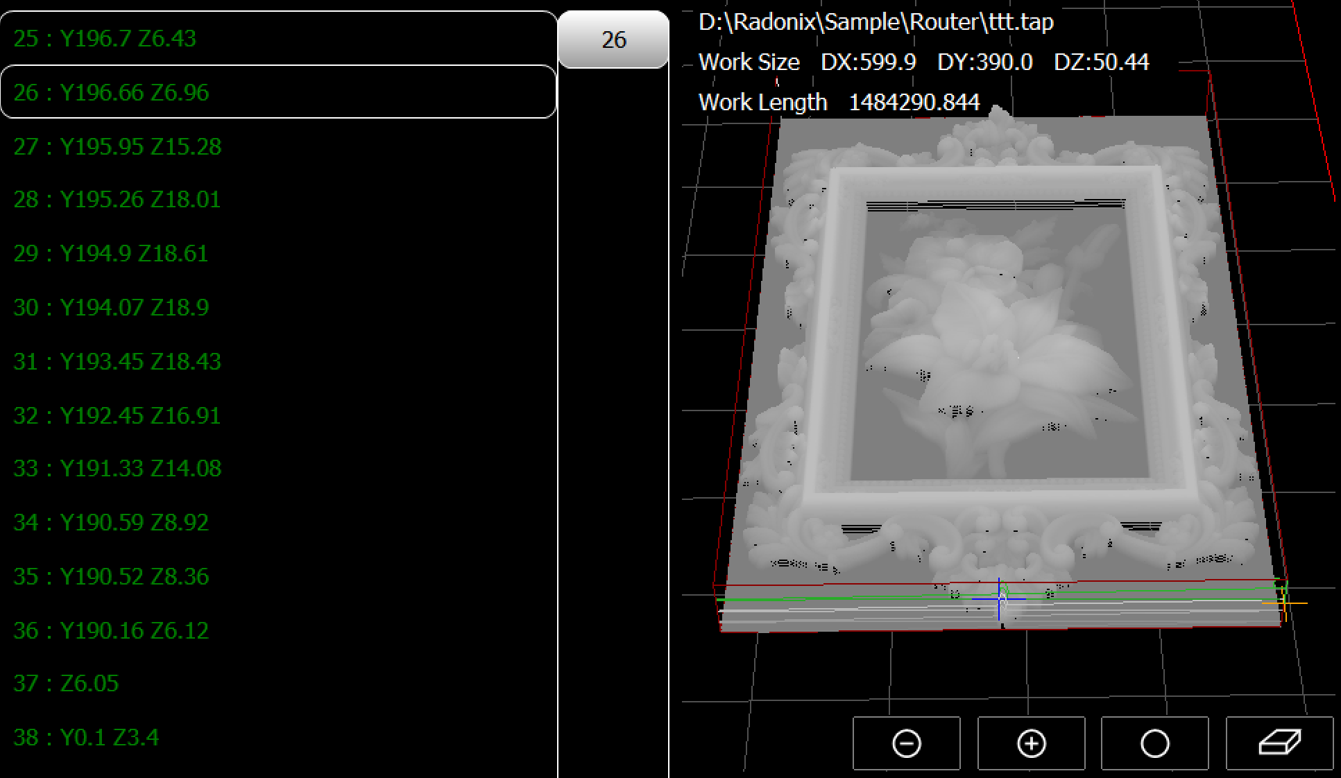
- Zoom and Pan Controls:
- + and - Buttons: Zoom in and out on the display.
- Circle Icon: switching between different mode.
- Box Icons (Bottom Right of Grid): control additional viewing or display .
Special Functions
- Support for Various Router Types:
- Up to 6 simultaneous axes for applications like wood, stone, milling, mold making, and dental work.
- Rotation Tool Center Point (RTCP):
- RTCP support ensures accurate rotary toolpath calculations.
- Multi-Spindle Head Support:
- Ideal for machines requiring multiple spindles.
- Automatic Tool-Changing Devices:
- Supports linear, rotary, and jack-type tool changers.
- Tool Offset Sensors:
- Automatic Z-axis tool offset sensing and referencing for precision.
- 3D Tool Path Display:
- Visualization of tool paths, including support for rotary axes.
- Loading Depth Restriction:
- Floor depth restrictions for controlled operations.
Initial Setup: Configuring Settings and Wiring for Peripheral Integration
In this section, it is essential to comprehend the configuration of the inputs and outputs to effectively manage their operation.
Applying Changes in Radonix
When making any changes in the Radonix Cam Pro software, it is essential to follow a specific process to ensure that all updates are properly applied and functional throughout the system. This process ensures that settings are saved and initialized correctly.
Steps for Applying Changes
- Make the Changes:
- Navigate to the appropriate section (e.g., Inputs, Outputs, System Settings).
- Modify the desired parameters or configurations.
- Press the Set Button:
- After making changes, click the Set button to confirm and apply them throughout the software.
- Close the Program:
- Completely close the Radonix Cam Pro software after saving changes.
- Reopen the Program:
- Restart the software to initialize the updated settings and ensure they are loaded properly.
Inputs and Outputs Structure
Inputs:
- Purpose: Inputs receive signals from various sensors or external controls (like limit switches, emergency stops, or user interfaces).
- Types: Common input types include digital (e.g., ON/OFF signals) and analog (e.g., varying voltage levels).
- Configuration: Inputs are configured to trigger specific responses in the CNC system. For instance, an emergency stop input might trigger all operations to halt immediately.
Outputs:
- Purpose: Outputs actuate machinery components, like motors, valves, or lights, based on the commands from the CNC system’s processing unit.
- Types: Outputs can be relay-based (for high power applications) or transistor-based (NPN or PNP for direct control with less power).
- Protection Features: As in Radonix models, outputs often have protections such as short-circuit prevention, overload protection, and error indication to ensure safe operation.
In summary, the CTRL + SHIFT + ALT + Delete shortcut is a powerful diagnostic tool for real-time inspection of your CNC system’s internal state. By utilizing this feature and reviewing additional information in Appendix 4, you can more easily troubleshoot and optimize your Radonix CNC machine’s performance.
Inputs and Outputs in Radonix Cam Pro
Location:
Inputs and outputs in the Radonix Cam Pro software are typically managed through a dedicated section of the software interface is located in Setting / System / Inports or Outports.
These settings allow users to configure and customize the behavior of the machine's physical and virtual components to meet specific operational needs.
Accessing Inputs and Outputs
- Navigate to the Settings menu.
- Select System to open the configuration options.
- Choose either Inports or Outports to access the respective settings.
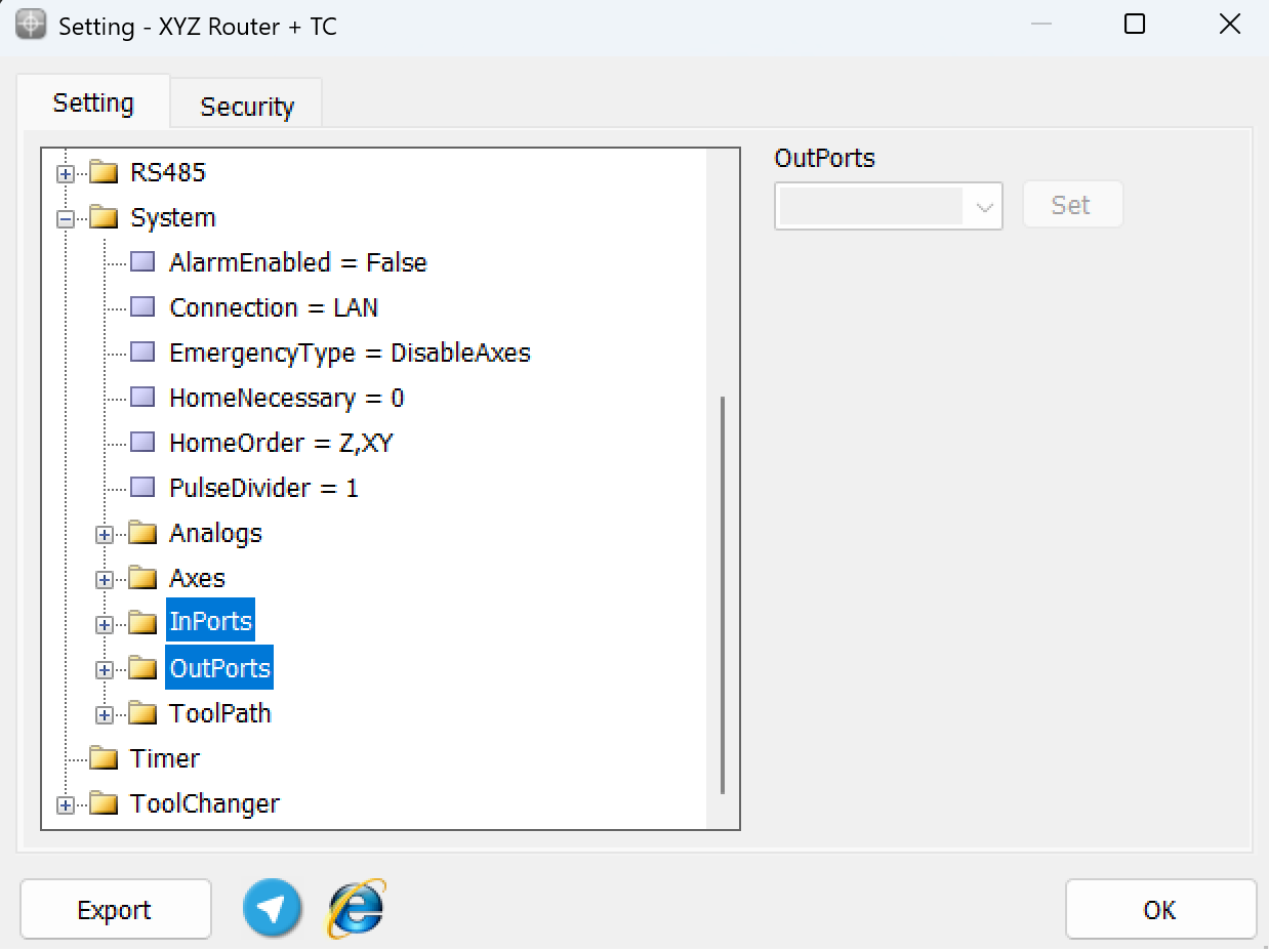
Expanding Input/Output Sections
- Beside each part (Inports or Outports), you will find a plus (+) button.
- Clicking this button will expand the section, revealing the configuration options for individual inputs or outputs.
How you can monitor all inputs and outputs together
Overview
In Radonix CAM-Pro software, you can quickly view the status of the controller’s internal variables, axes, inputs, and outputs using a special diagnostic shortcut. This is particularly helpful for troubleshooting issues related to sensors, axes movement, or output signals.
Shortcut: CTRL + SHIFT + ALT + Delete
Press CTRL + SHIFT + ALT + Delete to open an on-screen display that shows:
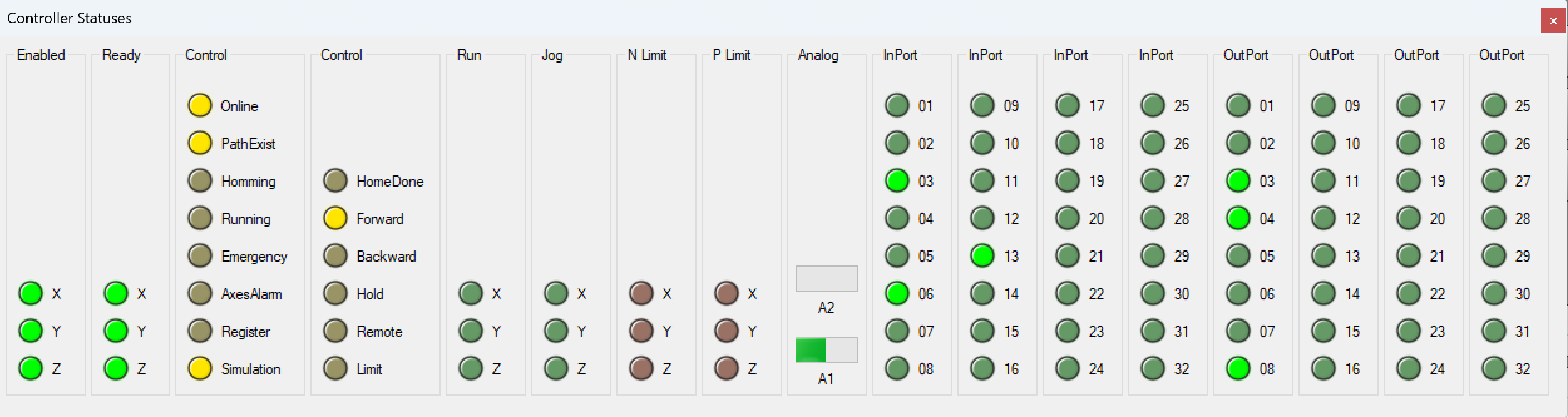
- Internal Variables:
- Real-time values of key parameters such as feed rates, acceleration values, and any custom variables used in your CNC programs.
- Axes Status:
- Current positions of the X, Y, Z (and any additional) axes.
- Movement states (e.g., jogging, homing, paused).
- Activation status (green lights) indicating whether each axis is online and responsive.
- Inputs and Outputs:
- A list of digital inputs (limit switches, sensors, emergency stops) and their live state (ON/OFF).
- A list of digital outputs (relays, spindle on/off signal, pneumatic valves) and whether they are currently active or inactive.
Usage Scenarios
- **Wiring Diagnostics:**Confirm that a limit switch or sensor correctly toggles from OFF to ON when physically triggered.
- **Axis Verification:**Check whether the software is correctly commanding each axis to move, and whether the axis is acknowledging motion.
- **Signal Confirmation:**Verify if the controller is sending the correct signal to external hardware (e.g., spindles, vacuum pumps, coolant systems).
Tips & Notes
- The CTRL + SHIFT + ALT + Delete shortcut is unique to the Radonix CAM-Pro software and is not the same as the standard Windows CTRL + ALT + Delete function.
- If nothing appears on your screen after using the shortcut:
- Ensure that Radonix CAM-Pro is running and the controller is powered on.
- Verify that you are using the correct key combination in the proper sequence.
- If you encounter persistent issues or see unexpected values in the diagnostic view, consult your system administrator or contact Radonix technical support.
Inputs
- In this section, we will examine the configuration of the Inputs.
Setting Up Inputs: General Overview
Configuring inputs in our CNC system is an essential step to ensure smooth operation, precise control, and safety. Inputs can be categorized into two main types based on their configuration and purpose: Hardware-Based Inputs and Software-Based Inputs. This flexibility allows the system to adapt to a wide range of applications and machine requirements.
1. Hardware-Based Inputs
Hardware inputs involve physical devices connected to the controller, enabling direct interaction with the machine's environment. These inputs are crucial for safety, machine control, and real-time feedback.
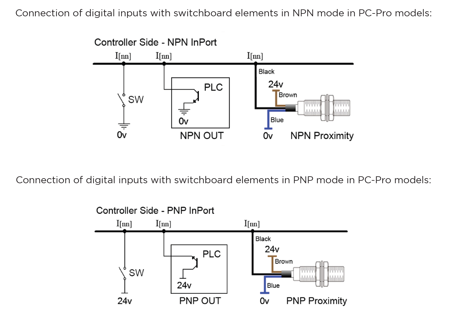
The digital inputs of Radonix controllers are named as I, where n is a number greater than zero and represents the input number. These inputs are isolated by optical couplers and have low noise tolerance due to their low impedance.
The digital inputs on Radonix controllers have the capability to switch between NPN and PNP modes depending on the output of the device or sensor. The mode changeover switch must be set to PNP position for devices with PNP output and NPN position for devices with NPN output.
In various branches of industrial automation, there are equivalent terms for PNP and NPN. Someexamples of these terms include:
NPN = Sink = Low Active
PNP = Source = High Active
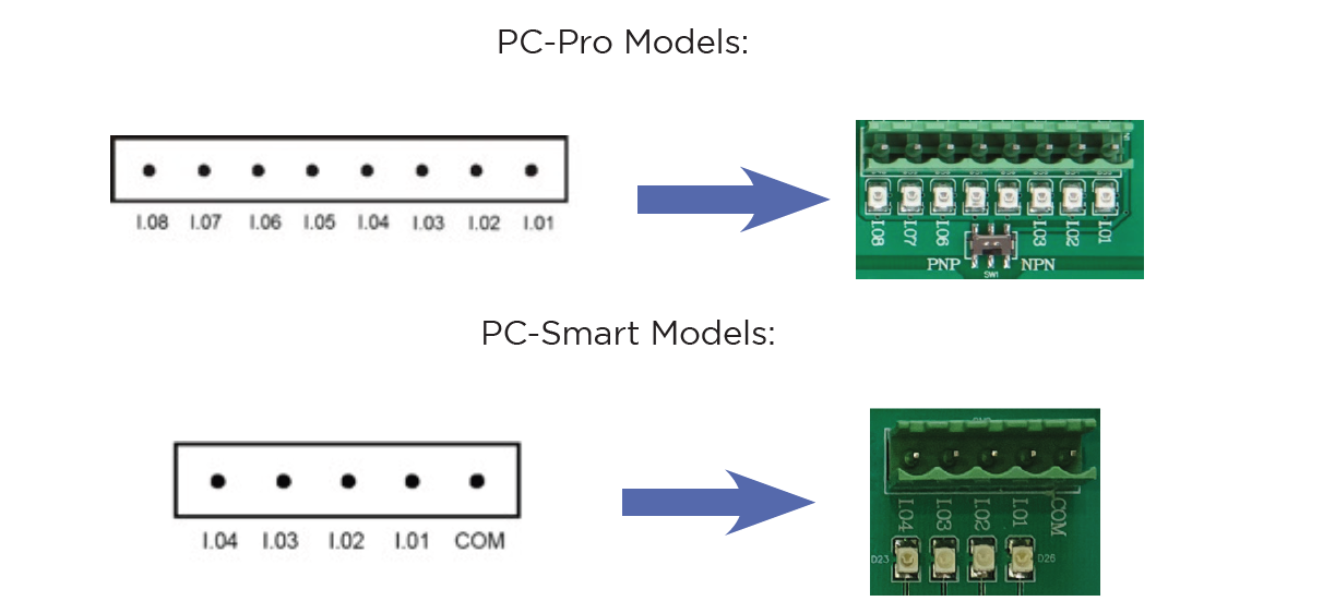
Switching Between PNP and NPN Modes in Radonix Systems
The ability to switch between PNP (positive logic) and NPN (negative logic) modes in Radonix controllers depends on the specific board model being used. This flexibility allows the system to be compatible with different wiring and sensor configurations.
- PC Pro LAN:
- A small DIP switch is present on the board.
- This switch allows users to toggle between PNP and NPN modes.
- How to Use:
-
Locate the DIP switch on the board.
-
Toggle the switch to the desired mode (PNP or NPN).
-
Ensure the board is powered off before making changes to prevent damage.
-
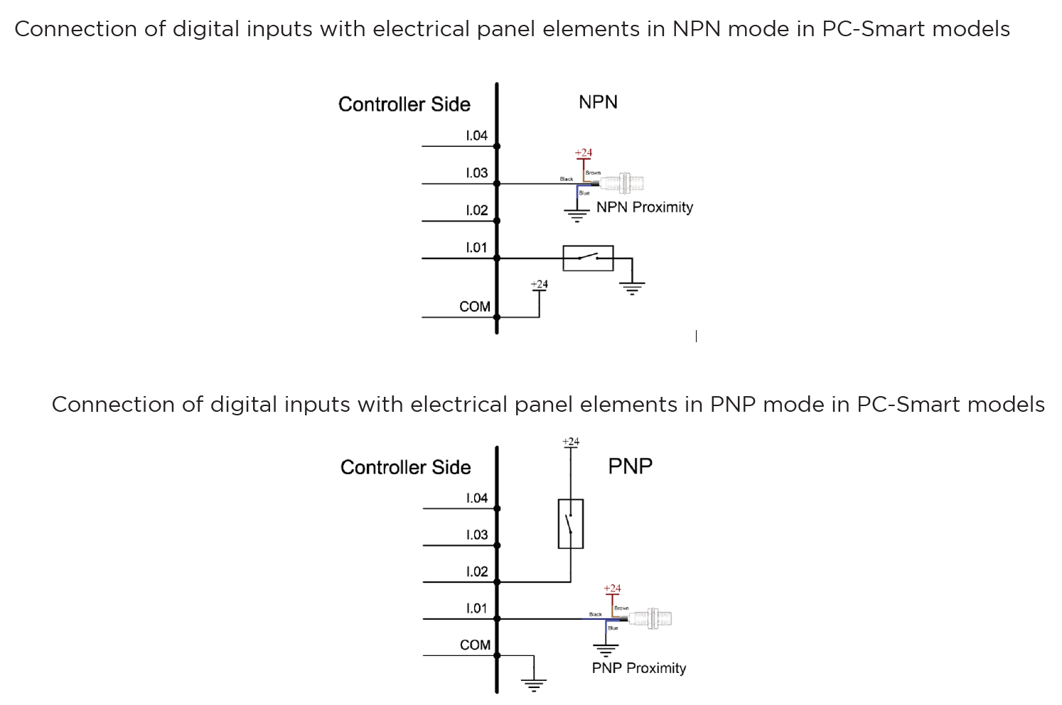
- PC Smart:
-
Instead of a DIP switch, the PC Smart model uses a Come Pin for each set of 4 input pins.
-
This pin allows you to define the input logic (PNP or NPN) for the corresponding inputs.
-
How to Use:
-
Connect the Come Pin to the appropriate voltage (positive for PNP or ground for NPN).
1.PNP Mode (Source Mode):
- If the COM pin is connected to 0V, the input pins will be triggered (turned ON) by a 24V signal.
- In this configuration, the sensor’s output wire must provide a 24V signal to activate the input.
2.NPN Mode (Sink Mode):
- If the COM pin is connected to 24V, the input pins will be triggered (turned ON) by a 0V signal.
- In this configuration, the sensor’s output wire must pull the input to 0V to activate it.
- If the COM pin is connected to 0V, the input pins will be triggered (turned ON) by a 24V signal.
-
Each group of 4 input pins has its own Come Pin, allowing for mixed configurations within the same board.
-
-
Examples of Hardware Inputs:
- Limit Switches: Define physical boundaries for axis movement.
- Home Sensors: Establish the reference (Home) position for the machine most of them are Proximity
- Emergency Stop Buttons: Ensure immediate halting of operations in emergencies.
- Other Proximity Sensors: Detect objects or tools in the machine's workspace.
- Push Buttons and Selector Switches: Trigger specific machine functions or modes.
- Scanners: Measure or detect specific properties, often used in specialized processes such as Glass or gold CNC operations.
Configuration Process:
- Connection: Physically connect the hardware component (e.g., a switch or sensor) to the designated input pin on the controller.
- Input Definition: Use the controller software to define the role of the input (e.g.,
HomePin,LimitPin, or a custom input for specific functions). - Polarity Settings:
- Set the input type as Normally Open (NO) or Normally Closed (NC) based on the connected hardware's default state.
- For example:
- An NC emergency stop button remains active (closed) until pressed.
- An NO proximity sensor activates (closes) only when an object is detected.
2. Software-Based Inputs
Software-Based Inputs provide simple logical functionality to configure arbitrary links and integrate them with related physical hardware .They facilitate quick and simple installation without the need for microprogramming. Users can simply select options from a list and configure settings to maximize efficiency.
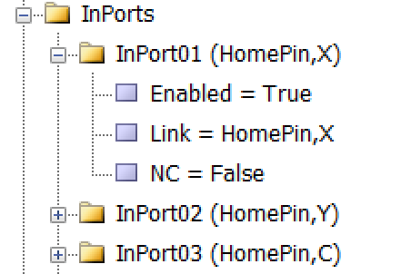
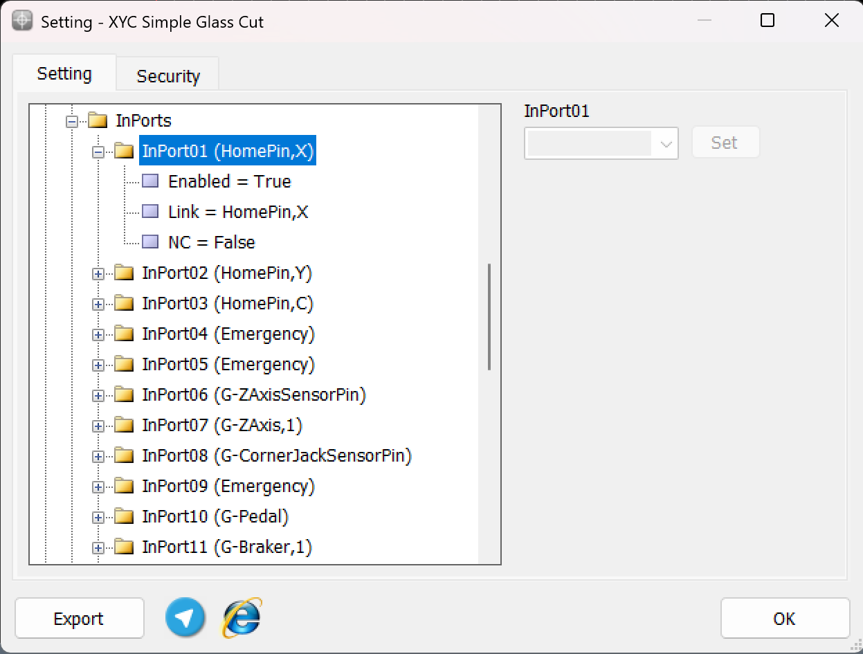
As illustrated in the figure, each input is divided into three sub-branches, as detailed below:
- Enable: This sub-branch can be set to two values: True or False.
- Link: Specifies the duty or task that needs to be performed or checked. This includes any device that can serve as an input, such as sensors, buttons, and switches.
- NC: Determines whether the specific input is Normally Open (NO) or Normally Closed (NC).
Examples of Software Inputs:
- Virtual Limit Switches:
- Use software parameters to define axis movement boundaries based on the machine's table size.
- Logical Triggers: Define conditional triggers for specific operations (e.g., When the axis reaches the limit switch ).
- Simulated Inputs: Use for testing or scenarios where physical components are unavailable.
Configuration Process:
-
Access Configuration Interface:
- Open the controller's software settings to manage inputs.
-
Define Parameters:
As an example to set limit Switch :
-
setting —→ System —→ In ports —→ Enabled= True
Linked = LimitPin,X
NC= True
-
Configure additional logical conditions for interlocks or simulations.
- Validate Settings:
- Test the software by CAM Pro TEST input configurations to ensure proper functionality and safety.
Setting Up Inputs
Simple and Intuitive Configuration
In Radonix system, configuring inputs or Outputs is designed to be as user-friendly as possible, without requiring any microprogramming or advanced technical knowledge. All you need to do is navigate to the Inputs section of the controller interface, open the settings drawer, and select the item you need to configure. The same process applies to other sections, such as Outputs or any other functional areas.
- Access the Desired Section:
- Go to the section you want to configure, such as Inputs or Outputs, depending on the functionality you are setting up.
- Open the Settings Drawer:
- Within the selected section, locate the specific input branch or subsection.
- Click or expand the settings drawer to reveal the available options.
- Select the Required Item:
- Choose the input type or functionality you want to configure (e.g., limit switch, home sensor, emergency stop, or custom inputs).
- Define the specific role for the input, such as
LimitPin, XorHomePin.
- Set Parameters Easily:
- Adjust the necessary parameters, such as polarity (Normally Open or Normally Closed), response delays, or logical behaviour, directly from the interface.
- Save and Test:
- Save your settings and validate them through the controller interface to ensure everything is functioning as intended.
- In the end in order to finalizing you have to close program to save everything
Key Features of the Configuration System
- No Microprogramming Needed: The intuitive design ensures you can make all necessary configurations without writing code or using low-level programming tools.
- Centralized Interface: Everything is accessible through a single, organized interface, making it easy to navigate between different sections.
- Flexibility: Configure both hardware and software inputs effortlessly, adapting the system to meet your specific operational needs.
- Error-Free Setup: The graphical interface minimizes the chances of errors, ensuring a seamless configuration process.
Essentially, once the interface is installed, it comes with a default setup, and everyone can change the order of the input ports. For instance, we include necessary Inports which are effective and suitable for the initial launch .
The first recommended step for providing protection against any errors or mistakes is to define the Emergency link. This can be connected to a button that either stops the motors or turns off the digital outports.
Outputs
In this section, we will examine the configuration of the Outputs.
Setting Up Inputs: General OverviewIn Radonix systems, Outports are critical components that manage the output signals controlling various peripherals, such as relays, actuators, alarms, and other devices. Outputs can be categorized into two main types based on their configuration and purpose: Hardware-Based Inputs and Software-Based outputs.
This flexibility allows the system to adapt to a wide range of applications and machine requirements.
1. Hardware-Based Outputs
Hardware outputs involve physical signals sent from the controller to external devices, enabling direct control of the machine’s environment. These outputs are critical for operational safety, machine actuation, and real-time command execution, ensuring efficient workflow and coordination within the CNC system.
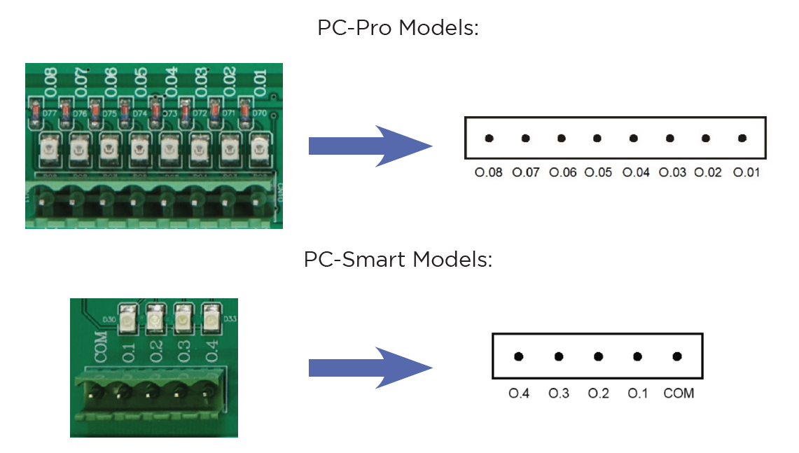
The digital outputs of Radonix controllers are named "O" , where n is a numerical identifier greater than zero and represents the output number .
Radonix controllers incorporate robust protection mechanisms for Outports to ensure durability, safety, and reliability. These mechanisms vary between different models, specifically the PC-Pro and PC-Smart boards, each with distinct protection features and failure handling processes.
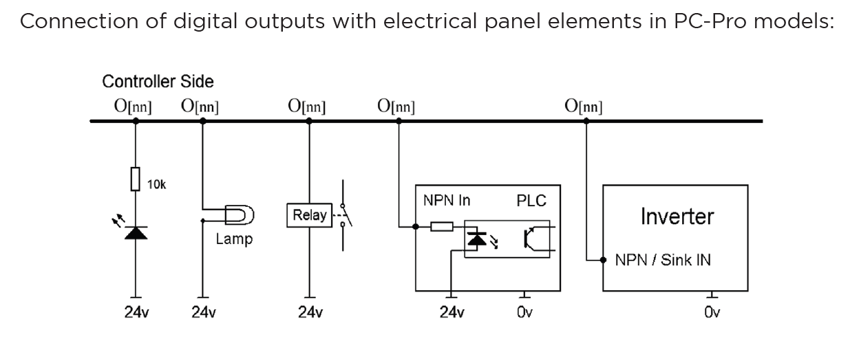
Output Behaviour in PC-Pro LAN Models
-
The PC-Pro LAN model outputs are fixed in NPN mode.
-
How It Works:
- When an output is ON, it provides 0 volts by pulling the signal to ground.
- When an output is OFF, it is in a high-impedance state, effectively disconnecting the circuit.
-
Wiring Consideration:
- Connected devices must be compatible with NPN logic, where the load receives voltage from a positive source and is activated when the output pulls the circuit to ground.
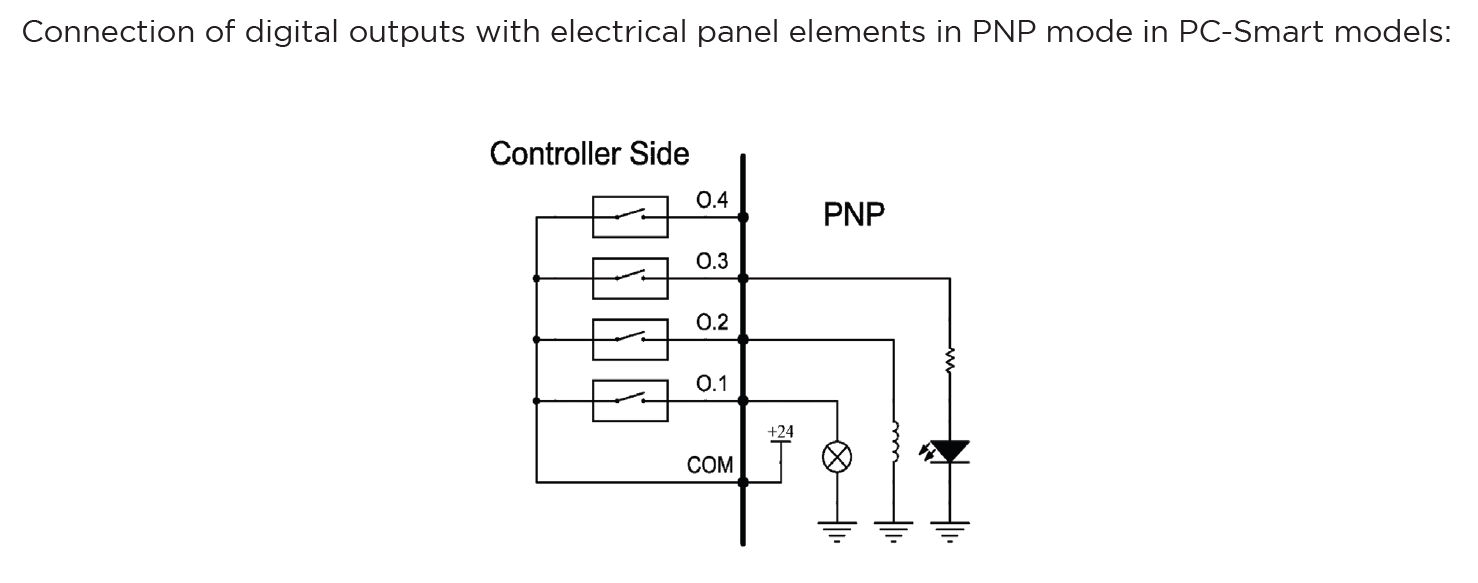
Output Behavior in PC-Smart Models
-
The PC-Smart model offers a flexible configuration where outputs can operate in PNP mode or NPN mode, depending on the connection of the COM Pin.
-
How It Works:
- The voltage provided by the outputs depends on what is connected to the COM Pin:
- COM Pin Connected to 24V: Outputs will provide 24 volts when activated.
- COM Pin Connected to Ground: Outputs will provide 0 volts when activated (NPN mode).
- The voltage provided by the outputs depends on what is connected to the COM Pin:
-
Flexibility:
- This design allows PC-Smart models to adapt to different wiring requirements and device logic preferences.

Configuration Process for Outputs:
- Connection:
- Physically connect the hardware component (e.g., relay, electric valve , Barke , alarm) to the designated output pin on the controller.
- Ensure proper wiring based on the required logic (PNP or NPN) and voltage compatibility.
- Output Definition:
- Use the controller software to define the role of the output (e.g.,
SpindleCWpin,Coolant,SpindelCoverpinor a custom output for specific functions). - Assign the output to its intended device or operation in the system settings.
- Use the controller software to define the role of the output (e.g.,
- Logic Settings:
- Set the output logic based on the connected device's requirements:
- Active High (PNP): The output sends voltage (e.g., 24V) when activated.
- Active Low (NPN): The output pulls the signal to ground (0V) when activated.
- Set the output logic based on the connected device's requirements:
- Testing and Validation:
- After configuring, test the output to ensure it operates as intended in CAM Pro Test application.
- Use a multimeter or other diagnostic tools to verify output voltage and behaviour.
2. Software-Based Outputs
Software-Based Outputs provide simple logical functionality to configure and integrate them with related physical hardware. These features are crucial for enhancing control capabilities. They facilitate quick and simple installation without the need for microprogramming. Users can simply select options from a list and configure settings to maximize efficiency.
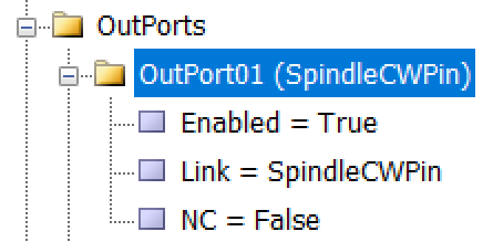
As illustrated in the figure, each output is divided into three sub-branches, as detailed below:
- Enable: This sub-branch can be set to two values: True or False.
- Link: Specifies the duty or task that needs to be performed or checked. This includes any device that can serve as an output, such as actuators, lights, and alarms.
- NC: Determines whether the specific output is Normally Open (NO) or Normally Closed (NC).
Examples of Software Outputs:
- Virtual Relays:
- Use software parameters to define activation boundaries for devices based on operational needs.
- Logical Triggers: Define conditional triggers for activating specific outputs (e.g., alarms or Relay for specific function ).
- Simulated Outputs: Employ these for testing or in scenarios where physical components are not available.
Configuration Process:
- Access the Configuration Interface:
- Navigate to the controller's software settings to manage outputs.
- Define Parameters:
-
To configure an output like an order to forward the VFD, enter parameters.
-
setting —→ System —→ Outports —→ Enabled= True
Linked = SpindleCWPin
NC= True
-
- Validate Settings:
- Test the configured software outputs to ensure they function correctly and safely, verifying their effectiveness in real-world applications.
Setting Up Inputs
In Radonix system, configuring inputs or Outputs is designed to be as user-friendly as possible, without requiring any microprogramming or advanced technical knowledge. All you need to do is navigate to the Inputs section of the controller interface, open the settings drawer, and select the item you need to configure. The same process applies to other sections, such as Outputs or any other functional areas.
Step-by-Step Configuration Process
- Access the Desired Section:
- Go to the section you want to configure, such as Inputs or Outputs, depending on the functionality you are setting up.
- Open the Settings Drawer:
- Within the selected section, locate the specific input branch or subsection.
- Click or expand the settings drawer to reveal the available options.
- Select the Required Item:
- Choose the input type or functionality you want to configure (e.g., limit switch, home sensor, emergency stop, or custom inputs).
- Define the specific role for the input, such as
SpindleCWPin
- Set Parameters Easily:
- Adjust the necessary parameters, such as polarity (Normally Open or Normally Closed), response delays, or logical behaviou, directly from the interface.
- Save and Test:
- Save your settings and validate them through the controller interface to ensure everything is functioning as intended.
- In the end in order to finalizing you have to close program to save everything
Installation and Setup Process
Radonix recommends following this detailed step-by-step guide for installing and configuring a Radonix CNC controller. The process encompasses everything from wiring the hardware to setting parameters in the software. This approach aims to guarantee a seamless installation experience for customers, addressing all critical components.
1. Wiring Components for a Radonix CNC Controller
- Main components overview
- Wiring the Main Power Supply
- Anti-Noise Measures for CNC Wiring
1. Main Components Overview
A typical CNC system includes the following components, all of which require precise and secure wiring:
- Radonix CNC Controller: The central control unit.
- Servo or Stepper Motors: Responsible for axis movement.
- Variable Frequency Drive (VFD): Controls the spindle motor.
- Sensors:
- Home Sensors for axis referencing.
- Limit Switches for boundary control.
- Emergency Stop (E-Stop): Ensures immediate shutdown during emergencies.
- Power Supplies: Provides regulated power for different components.
- Peripheral Outputs: Includes relays, coolant pumps, and alarms.
2-Wiring the Main Power Supply
Choosing the suitable Power Supply
-
Controller Power Supply:
It is recommended to use 24V switching power supplies to power the Radonix controllers. Calculating Power Supply Current To determine the required power supply current in the electrical panel, the current consumption of each element connected to the power supply must be calculated. For example, if there are 4 relays, 3 pneumatic solenoid valves, and a controller in a switchboard, the current consumption can be determined using Ohm’s law (V=I*R). The electric currents should be calculated and their sum considered as the current of the power supply, along with a confidence factor of a few percent. For example, if the current consumption of the relays is 0.1A and that of the solenoid valves is 0.25A, the total current can be calculated as follows: Total current = controller current + relay current + solenoid valve current IT = 0.5 + 4 * 0.1 + 3 * 0.25 = 1.65A
3-Anti-Noise Measures for CNC Wiring
Electromagnetic interference (EMI) or electrical noise is a common issue in CNC systems, particularly when wiring sensitive components like controllers, servo drives, and sensors. Noise can disrupt signals, cause erratic machine behaviour, and even damage components over time. Implementing robust anti-noise measures is critical for ensuring the reliable and precise operation of your CNC machine.
Sources of Electrical Noise
- High-Frequency Devices:
- Variable Frequency Drives (VFDs)
- Switching power supplies
- High-Power Components:
- Spindle motors
- Servo and stepper motors
- Long Cables:
- Longer cables act as antennas, picking up EMI.
- Proximity to Power Lines:
- Signal and power cables running close together can cause interference.
Key Anti-Noise Measures
- Use Shielded Cables
- Purpose: Shielded cables reduce the effect of electromagnetic interference on sensitive signals.
- Implementation:
- Use twisted-pair shielded cables for signal lines like Pulse+, Pulse-, Direction+, Direction-, and sensor signals.
- Connect the shield to ground at one end only to avoid ground loops.
- Separate Signal and Power Cables
- Purpose: Prevent high-power cables from inducing noise in low-power signal cables.
- Implementation:
- Route signal cables (e.g., sensor and control signals) separately from power cables (e.g., motor power and VFD output).
- Maintain at least 10-15 cm of separation between these cable types.
- Use different cable trays or conduits for power and signal lines.
- Proper Grounding
- Purpose: A well-designed grounding system minimizes noise and protects components.
- Implementation:
- Create a central grounding point in the electrical box, often referred to as a grounding bus bar.
- Ensure all grounding wires (controller, drives, motors, etc.) connect to this central point.
- Avoid daisy-chaining ground connections, which can introduce noise.
- Install Ferrite Beads
- Purpose: Ferrite beads filter out high-frequency noise on signal and power cables.
- Implementation:
- Clip ferrite beads onto signal and control cables near the controller or servo drives.
- Use multiple beads for particularly noisy environments.
- Proper VFD Wiring
- Purpose: VFDs are a significant source of electrical noise and require special attention.
- Implementation:
- Use shielded cables between the VFD and spindle motor.
- Ground the cable shield at the VFD end.
- Install line filters or chokes on the VFD input and output to suppress noise.
- Shorten Cable Lengths
- Purpose: Longer cables are more susceptible to picking up noise.
- Implementation:
- Keep cable lengths as short as possible without compromising flexibility.
- Avoid unnecessary slack or loops in the wiring.
- Use Isolated Power Supplies
- Purpose: Prevent noise from one system affecting another.
- Implementation:
- Use separate, isolated power supplies for sensitive components like sensors, encoders, and the controller.
- Ensure power supplies are adequately rated and properly grounded.
- Use Optical Isolation
- Purpose: Protect the controller from noise on external connections.
- Implementation:
- Use opto-isolators for connections to external devices like sensors, relays, or switches.
- Many Radonix controllers have built-in optical isolation for inputs and outputs.
- Secure Connections
- Purpose: Loose connections can act as noise sources.
- Implementation:
- Check all connectors for tight and secure connections.
- Use locking connectors where possible to prevent accidental disconnections.
- Line Filters and Surge Protectors
- Purpose: Suppress high-frequency noise and protect against voltage spikes.
- Implementation:
- Install EMI line filters on the AC mains supply.
- Use surge protectors on power inputs to the controller and VFD.
2. Software Configuration: Bringing the System to Life
Step 1: Install Radonix Cam Pro
- Download and install the software on your PC.
- Upon turning on the controller, observe the LEDs on the LAN port: one should remain steady, while the other blinks.
- Connect the Radonix controller to the computer via a LAN or USB cable.
Step 2: Initial Setup
- Open the software and initialize the system.
- Perform a factory reset to ensure default settings are applied.
Step 3: Configure Inputs
- Navigate to Settings > System > Inports.
- Assign roles to each input:
EmergencyStopfor the E-Stop button.HomePin, X Or Y Or Zfor home sensors.LimitPin, X Or -Xfor limit switches.
- Test each input by activating it physically and observing the software response.
Step 4: Configure Outputs
- Navigate to Settings > System > Outports.
- Assign roles to each output:
SpindleControlfor spindle activation.Coolantfor the coolant pump.
- Test outputs by toggling them in the software and observing the connected devices.
Step 5: Axis Calibration
- Go to Settings > System > Calibration.
- Enter parameters for each axis:
- Steps per Unit: Based on lead screw pitch, motor steps, and encoder resolution.
- Max Travel: Define the maximum travel distance for each axis.
- Test calibration by commanding movements and measuring actual travel distances.
3. Emergency Stop (E-Stop):
A critical response mechanism in industrial settings used to halt machinery and equipment immediately in order to protect against imminent danger. This action is typically engaged through an emergency stop button or switch that, when activated, interrupts the power supply and ceases all operations, effectively minimizing the risk of accidents, injuries, or damage to the machinery and personnel.
Configurable Emergency Mode
An advanced feature in control systems that allows users to define and set up custom emergency responses through the system settings. This mode can be programmed to engage different levels or types of responses depending on the nature and severity of the threat detected.
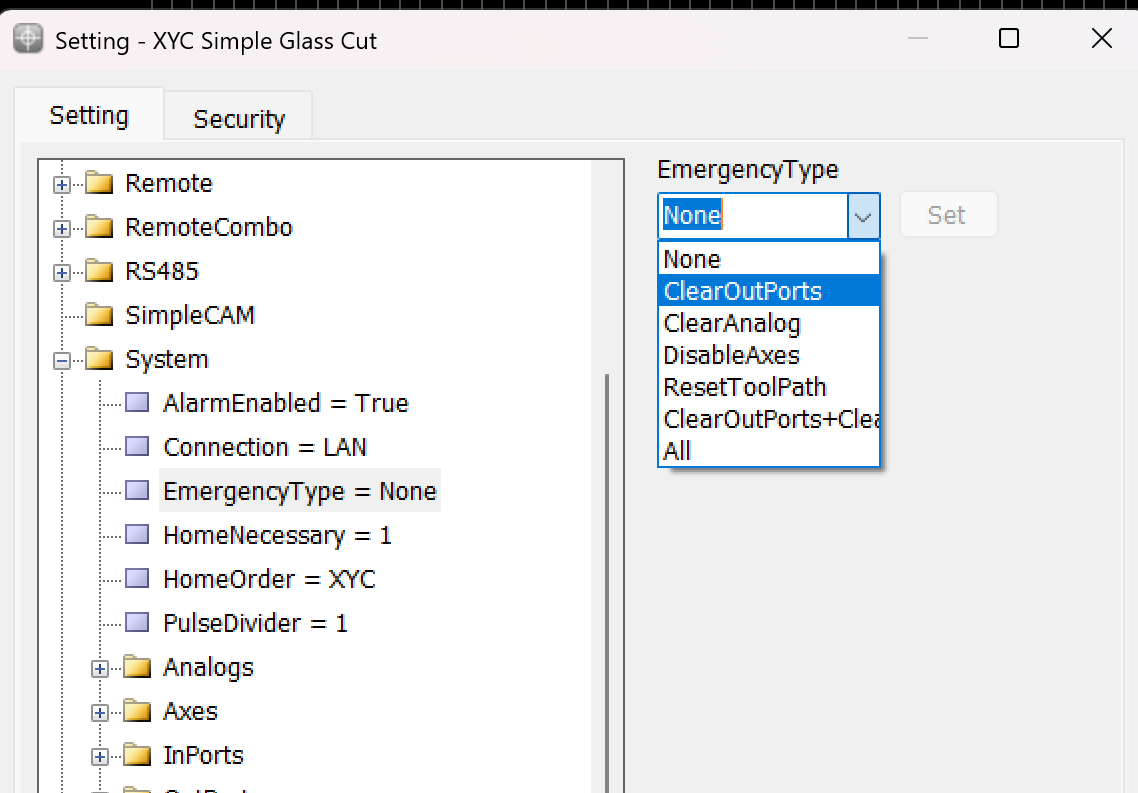
This variable is used to determine the operation that occurs when the Emergency button is pressed.
- None: When this mode is selected, the machine operation is similar to a pause. The device stops all activities but cannot be resumed from the same point if this mode is triggered.
- ClearOutPorts: Activating this mode stops the axes and turns off all digital output ports of the controller. This ensures that no further commands affect the machine's operation until reset.
- ClearAnalog: This mode stops the axes and turns off all analog outputs. It's used to ensure that any variable outputs controlling aspects like tool pressure or spindle speed are deactivated.
- DisableAxes: In this emergency mode, the axes of the machine are stopped and become inactive, which means the motors that drive the axes are disengaged, allowing them to move freely if manually pushed but not under power.
- ResetToolPath: This mode stops the axes and resets the toolpath to the start of the program. This is useful in scenarios where the process needs to be started from the beginning, either to prevent damage or to correct an error.
- ClearOutPorts+ClearAnalog: This comprehensive emergency mode combines the effects of ClearOutPorts and ClearAnalog, stopping all digital and analog outputs, disabling the axes, freeing the motors, and resetting the toolpath to the first coordinate. This is effectively a full reset of the system's operating state.
- All: Selecting "All" activates all the above emergency responses, providing the maximum level of immediate system shutdown. All outputs, both digital and analog, are turned off; axes are stopped and freed; and the toolpath is reset.
4. Home Sensors
****Home sensors are so crucial for positions it means that thanks to these sensors the position become meaningful , they are impact in defining table size the sensors are machine zero point or machine origin point when axis reach the sensors the controller detect them and it causes that a red table is created in Black Grid space so with this option each point in this area has its own position than sensors in each axis
Indeed, home sensors are integral to the function and accuracy of CNC machines. Let's explore further how these sensors interact with the CNC controller and influence the machine workspace setup:
Role and Functionality of Home Sensors:
- Defining the Origin: Home sensors establish the machine's zero point or origin. This point serves as the reference for all other positions within the machine's operational space. It ensures that the machine knows the starting point for all axes (typically labelled X, Y, and Z).
- Impact on Table Size and Work Area Definition: The detection of the home position by these sensors directly impacts the definition of the machine’s table size. This is because the machine controller uses the origin point to calculate and define the extents of the machine’s operational area or table. The movements and operations of the machine are confined within these calculated boundaries to ensure precision and to prevent the machine from moving beyond its capable limits, which could cause damage or errors.
- Visualization on Controller Interface: When the home sensors are triggered, the CNC controller can visually depict this on its interface, often illustrated as a "red table" laid out on a "black grid" background. This visual representation helps operators to see and understand the active working area of the machine. It shows where tools can safely travel and operate, providing a clear demarcation of the workspace.
- Positional Accuracy: Each point within this defined red table area has a specific position relative to the machine’s origin point, determined by the home sensors on each axis. This arrangement allows for precise control over the machine's movements and operations, ensuring that every motion made by the machine is accurately accounted for relative to the origin, enhancing both the precision and reliability of the work performed.
- Operational Reliability: Regularly using home sensors to reestablish the machine’s origin point helps maintain operational accuracy and reliability, crucial for long-term consistent output, especially in precision-dependent applications.
Overall, home sensors not only provide a safety mechanism by defining the limits of machine operation but also enhance operational precision by establishing a clear and reliable reference point for all machining tasks. This setup ensures that every point within the operational area is accurately positioned relative to the origin, making the machine's functioning both predictable and precise.
To ensure precise cessation of axis movement after issuing the Home command, the appropriate input links must be configured prior to pressing the Home button, as depicted in the above explanation. This configuration ensures that the machine accurately detects the home position for each axis.
For example:
-
The input HomePin,X is assigned to detect the X-axis home position. This means that when the X-axis sensor aligns in front of its designated home sensor, the system identifies it as the home position.
-
Similarly, other axes such as Y , C , Z require their respective input links, such as HomePin,Y or HomePin,C, to be properly set based on the machine's axes and sensor alignment.
This structured setup allows the machine to halt each axis movement accurately when it reaches its home position, ensuring safe and reliable operation during homing procedures.
5. Set Max course and Min course
The concept of positive and negative direction is inherently tied to the Max Course and Min Course values. Movement toward the Max Course is considered positive, while movement toward the Min Course is considered negative.
In the context of homing, the Home direction becomes predictable based on these definitions. When the operator presses the Home button, the axis moves to locate the home sensor. If the Home Direction is set to positive, the axis will travel toward the Max Course to detect the home sensor at the maximum end. Conversely, if the Home Direction is set to negative, the axis will travel toward the Min Course to detect the home sensor at the minimum end.
This setup ensures that positive movement aligns with increasing values toward the Max Course, while negative movement aligns with decreasing values toward the Min Course.
6. Limit pin
In CNC machines, limit pins serve as an essential safety feature to prevent the machine axes from exceeding their physical boundaries. These pins are linked to hard limit switches, which are mechanical or sensor-based devices that stop the machine when triggered.
While Radonix controllers also provide soft limits within the software settings, hard limits add an extra layer of protection and ensure the machine operates safely in unexpected situations.
Key Points about Limit Pins
-
Hard Limits:
- Hard limits rely on physical limit switches installed on the machine.
- When an axis reaches the limit switch, the corresponding input link (e.g., G-LimitPin,X, G-LimitPin,Y, or G-LimitPin,Z) is triggered.
- The machine automatically stops to avoid damage to mechanical components.
-
Soft Limits:
- Soft limits are defined within the Radonix settings.
- The operator sets the allowable movement range for each axis through software, ensuring the axis does not move beyond these defined boundaries.
- These limits are monitored digitally and act as a preventive measure before reaching the physical hard limits.
-
Dual Safety Mechanism:
- Combining hard limit pins with soft limits ensures maximum protection:
- Soft Limits act as the first line of defense to stop movements within software-defined boundaries.
- Hard Limits serve as a final physical safeguard to prevent any accidental overrun of the machine axes.
- Combining hard limit pins with soft limits ensures maximum protection:
Configuration of Hard Limit Pins
To set up hard limits in Radonix controllers:
- Navigate to System > InPorts in the Radonix software.
- Assign the input links for the respective limit switches:
- G-LimitPin,X for the X-axis hard limit.
- G-LimitPin,Y for the Y-axis hard limit.
- G-LimitPin,Z for the Z-axis hard limit.
- Ensure the Enabled parameter is set to True.
-
limitPin,X
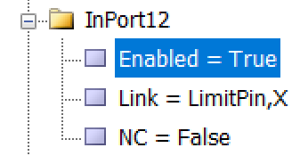
LimitPin,-X /// LimitPin,Y /// LimitPin,-Y /// LimitPin,Z /// LimitPin,-Z
-
7. Calibration
calibration refers to the process of aligning the motion value of an axis with one of the standard units or with a specific value. Common units in industrial devices are usually millimeters, centimeters, meters, inches, feet, degrees, etc., which are available for use based on the need. Therefore, the concept of calibration for the millimeter unit can be expressed as the alignment of the motion value of the desired axis with the millimeter unit. That is, in the case of measuring with measuring tools, the numerical value of the motion of the axis should be consistent with the measured value in millimeters.In Radonix controller, each axis has the ability to calibrate separately, and even the axes can be calibrated in different units. The variable representing the calibration factor in this controller is the Step variable, which to access it, you need to open the Radonix software and after opening the Setting window, go to the System branch and then the Axis" sub-branch ( represents the number between 1 to 6, which specifies the axis number.)This part can fell in categories stepper and servo motors so due to in this categorizing there are different strategies***
Servo motors
A servo motor is a type of rotary actuator or linear actuator that allows for precise control of angular or linear position, velocity, and acceleration. It typically includes a motor coupled to a sensor for position feedback. Servo motors are essential in applications where precise positioning is required, such as in robotics, CNC machinery, and automated manufacturing. They use feedback signals to adjust motion parameters and can be controlled through servo mechanisms that utilize error-sensing feedback to correct performance.Electronic Gear box:An Electronic Gear Box is an integral component in modern servo systems, especially in applications that involve servo motors, like those used in automation and robotics. This technology essentially functions as a virtual gearbox that adjusts the speed and torque of a motor electronically, rather than mechanically. By manipulating the frequency and amplitude of the motor’s input signals, an electronic gearbox can change the output characteristics of the motor to suit specific tasks without needing physical gear changes.Next step is essential for this subject is : Encoder ResolutionEncoder Resolution is a fundamental specification of servo motors, indicating the number of pulses an encoder emits for each complete revolution of the motor's shaft. This specification, expressed in pulses per revolution (PPR), is crucial for defining the precision with which the motor's position, speed, and acceleration can be controlled.For instance, the Delta servo motor's B2 model features an encoder resolution of 160,000 pulses per revolution. This means that for every full turn of the motor shaft, the encoder generates 160,000 distinct signals. In contrast, the A2 model from the same brand boasts a much higher resolution of 1,280,000 pulses per revolution. This higher resolution allows for even finer control and more precise adjustments, which is essential in applications requiring meticulous positioning and detailed motion control.High-resolution encoders are particularly beneficial in fields like robotics, CNC machinery, and automated assembly lines, where exact movements are paramount. The greater the encoder resolution, the smaller the movement that can be detected and controlled, enhancing the system’s accuracy and the quality of the output. This capability is crucial for optimizing the performance of high-precision tasks, ensuring that each component operates within tight tolerances and adheres to strict quality standards.Understanding and setting the encoder resolution appropriately is a critical first step in the calibration of automated systems. It ensures that the machine operates smoothly and that each part produced meets precise specifications, thereby reducing errors and increasing overall efficiency in manufacturing processes. This detailed control over motor movements is what makes modern automated systems capable of performing complex tasks with high reliability and accuracy.***General Guide to Setting the Electronic Gear Ratio (E.G.) in Servo Drives****OverviewConfiguring the Electronic Gear Ratio (E.G.) for servo drives is crucial for optimizing their performance in applications requiring precise motion control. This guide provides a generic approach to setting E.G. in servo drives, using the Delta B2 servo drive as a specific example to illustrate the process.
Requirements
- Servo drive with an integrated encoder
- Controller capable of generating pulse signals (e.g., a CNC controller)
- Technical specifications for both servo drive and controller
Step-by-Step Configuration
Step 1: Understand Encoder Resolution
- Objective: Recognize the encoder resolution, which is the number of pulses needed for one complete rotation of the servo motor's shaft.
- General Info: Encoder resolution is specified in pulses per revolution (PPR). It determines the precision with which the servo drive can control the motor position.
Step 2: Calculate Motor Speed in Rounds Per Second
- Objective: Convert the desired motor speed from RPM (revolutions per minute) to RPS (revolutions per second) to match the controller's output frequency.
- Procedure:
- Formula: RPS=RPM/60
- This calculation adjusts the time base from minutes to seconds, facilitating synchronization with pulse output.
Step 3: Determine Required Pulses Per Second
- Objective: Calculate the total pulses per second required based on the RPS and encoder resolution.
- Procedure:
- Objective: Calculate the total pulses per second required based on the RPS and encoder resolution.
- Procedure:
-
Multiply the RPS by the encoder resolution to get the required pulses per second.
-
Example Formula: Pulses per Second=RPS × Encoder Resolution
Pulses per Second=RPS ×Encoder Resolution
-
Step 4: Set the Electronic Gear Ratio (E.G.)
- Objective: Adjust the electronic gearing to enable the controller's output to meet the servo motor's pulse requirements.
- Procedure:

E.G.=Required Pulses / Controller’s Pulse Capability- Adjust the controller's settings to match the calculated E.G. ratio.Example: Delta B2 Servo Drive
-
Motor Speed: 3000 RPM
-
Encoder Resolution: 160,000 PPR
-
Controller's Pulse Capability:** 500,000 pulses per second
-
Calculation:- Convert RPM to RPS: 3000 / 60 = 50
-
Required Pulses: 50×160,000 = 8,000,000
8,000,000 pulses per second=50×160,0008,000,000 , \text{pulses per second} = 50 \times 160,000
-
E.G.: E.G.=16=8,000,000 / 500,000
E.G.=16=8,000,000500,000\text{E.G.} = 16 = \frac{8,000,000}{500,000}
-
Set E.G. Ratio: 16:1
Testing and Validation
- Objective: Ensure that the servo system functions correctly under the new settings.
- Procedure:- Conduct a test run to check the accuracy and responsiveness of the servo drive.
- Observe the motion to confirm that it aligns with expected parameters.Additional Notes
- Refer to specific servo drive manuals for detailed specifications and advanced settings.
- Regular maintenance checks and recalibration are recommended to sustain optimal performance.
- Procedure:- Conduct a test run to check the accuracy and responsiveness of the servo drive.
-
This comprehensive approach ensures that various types of servo drives can be efficiently integrated and operated in systems requiring high precision, such as in automation and robotics.
Stepper motors
A stepper motor is an electromechanical device that converts electrical pulses into discrete mechanical movements. It operates on the principle of electromagnetism, achieving precise movement and positioning by rotating in fixed step increments. This feature makes stepper motors ideal for applications requiring highly accurate and controlled movements such as 3D printers, CNC machines, and robotics. Stepper motors are favored in systems that require simple, open-loop control for precise short-distance or limited-angle applications.
stepper motor drivers often include DIP (Dual In-line Package) switches that allow users to configure specific settings for motor operation. These switches are critical for adapting the stepper motor's performance to the needs of a particular application. Here's a breakdown of common settings that can be controlled via DIP switches on a stepper motor driver:
Common DIP Switch Settings on Stepper Motor Drivers:
- Microstepping:
- Microstepping is a method of controlling stepper motors so they move in smaller increments. This results in smoother motion and higher resolution positioning. DIP switches allow for setting different microstepping configurations (e.g., full step, half step, quarter step, etc.).
- Current Setting:
- To optimize performance and efficiency, the current output to the stepper motor can be adjusted using DIP switches. This helps match the current to the motor's specifications to prevent underperformance or overheating.
- Decay Mode:
- Decay mode settings control how quickly the motor's current decreases in its off cycle. Proper decay mode settings can improve the performance and response time of the motor, especially at higher speeds or varying loads.
- Torque Settings:
- Some drivers allow the torque output of the motor to be adjusted via DIP switches. This setting is crucial when different loads or pressures are expected on the motor during operation.
How to Use DIP Switches:
- Refer to the Manual: Always check the stepper motor driver’s manual for specific instructions on what each DIP switch controls. This guide is essential for understanding how to correctly set the switches according to your needs.
- Set Before Powering: It’s important to set the DIP switches when the driver is powered off to avoid damaging the motor or the driver.
- Testing and Adjustment: After setting the DIP switches, run tests to ensure that the motor operates as expected under load. Adjust the settings if necessary to achieve the desired performance.
Indeed, setting the DIP switches to the highest microstepping value available on the stepper motor driver is often recommended by experts to achieve the smoothest movement possible. This practice is especially prevalent in applications where precision and smoothness are critical, such as in high-precision machining, robotics, or medical equipment. Here’s a closer look at why this recommendation is prevalent and how to implement it effectively:
Why Set to Highest Microstepping Value?
- Increased Resolution and Smoothness:
- Higher microstepping values increase the number of steps the motor takes to complete one full revolution. This results in smaller step increments, which smooths out the motion, reducing vibrations and resonance that are more noticeable at lower microstepping settings.
- Reduced Mechanical Noise:
- Smaller step increments also contribute to quieter operation. The smoother transition between steps minimizes the noise produced by sudden movements in stepper motors, which is beneficial in noise-sensitive environments.
- Enhanced Positional Accuracy:
- Although microstepping increases resolution, it's important to note that it does not inherently increase the positional accuracy due to potential step errors accumulating over time. However, in practical applications, finer steps allow for more precise control over motor positioning, which can be crucial for delicate operations.
Now based on this E.G calibration process can be feasible through two ways
1. Radonix CAM Calibrator and Measurement
In this calibration method, the basis is measurement with measurement tools and equipment. Therefore, the accuracy of the measuring tool, measurement accuracy, and mechanical errors of the device directly affect the quality of calibration. Although this method is not as precise as computational methods, it is a widely used method due to the lack of information on motors, gearboxes, pulleys, and gear wheels, whichare sometimes not available. The basis of this method is measuring the displacement value for a specific number of pulses. To facilitate, improve accuracy, and speed up calibration using the measurement method, Radonix has provided a free software called CAM-Pro Calibrator, which is automatically installed with the main Radonix software. Based on the physical displacement measurement of the axis and the required number of pulses for this displacement, the software calculates the step value.
Since pulse counting in this method is the responsibility of the controller, there is no error in pulse measurement. Therefore, the measurement accuracy in this method is directly related to the physical measurement accuracy. In addition, the greater the distance between the two measured points, the larger the pulse value will be, which means the denominator will increase, and according to the constant error, the overall step value obtained will be more accurate. Therefore, calibrating based on two points will result in more accurate results.
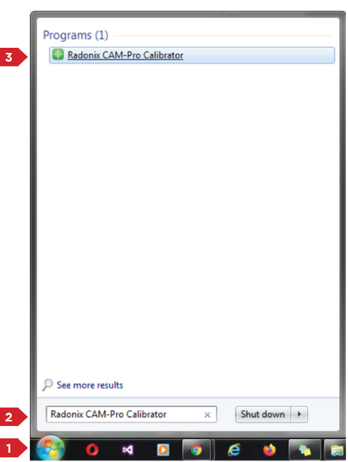
Introduction to CAM-Pro CalibratorAs explained in the previous section, the CAM-Pro Calibrator software is installed along with the CAMPro software. There are two ways to find the Calibrator software after installation. According to the first method, simply go to the installation location of the software, which is usually in the C drive of Windows by default, then go to the (x86) Program Files folder, open the Radonix folder, and the CAMProCalibrator software is visible in the Radonix CAM-Pro file. According to the second method, simply go to the Start menu and search for Radonix CAM-Pro Calibrator in the Search option.
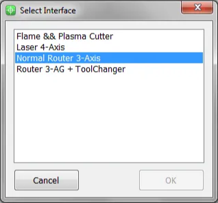
This program consists of two windows. The first window only appears if there are multiple active interfaces on a computer (Figure 3). Through this window, you can select the desired interface and launch it by pressing the 'Ok' button. If there is only one active interface on the computer, the interface selection window will not open, and the main window will open directly.
When you open the CAM-Pro Calibrator software, you will see Figure (4), which components are as follows:
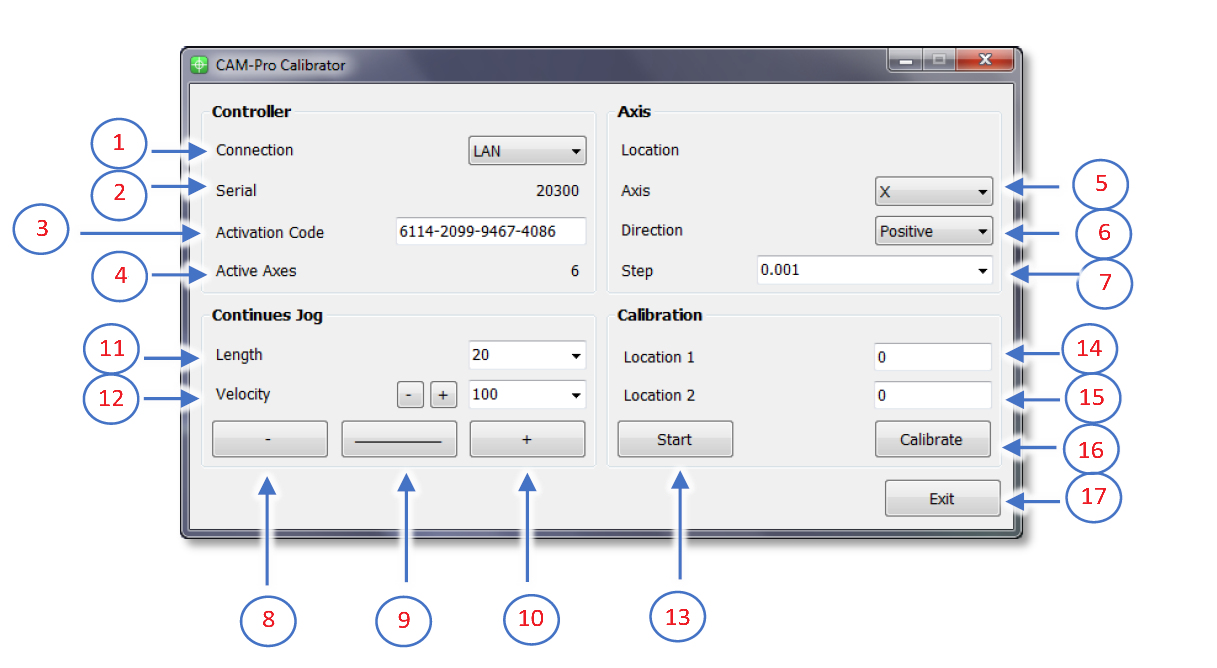
- Connection:
- ProLan controllers must be set to LAN mode.
- ProUSB controllers must be set to USB mode.
- Serial:
- Displays the controller's serial number.
- Activation Code:
- Displays the 16-digit code used to activate axes.
- Active Axes:
- Shows the number of activated axes using the activation code.
Axis Section
5.Axis:
- Allows selecting the desired axis for calibration.
6.Direction:
- Select the appropriate movement direction for standard axes:
- Negative: Movement towards the negative direction.
- Positive: Movement towards the positive direction.
7.Step:
- Sets the step size for calibration or output pulses. After calibration, the step is automatically recorded in the settings.
Continuous Jog Section
8.Negative Jog:
- Enables manual movement in the negative axis direction.
9.Jog Mode:
- Allows selecting the jog movement type:
- Continuous: Smooth, uninterrupted movement.
- Incremental: Moves in defined steps.
10.Positive Jog:
- Enables manual movement in the positive axis direction.
11.Length:
- Defines the incremental movement distance when the Incremental mode is active.
Velocity Section
12.Velocity:
- Used to set the speed for manual movements.
- The positive and negative buttons next to the Velocity option increase or decrease the speed of manual movements.
Calibration Section
13.Start:
- Button to initiate the calibration process.
14.Location 1:
- Used to set the initial position for calibration.
- This position must be relative to a fixed point on the measured axis.
15.Location 2:
- Used to set the final position for calibration.
- This position must also be relative to a fixed point on the measured axis.
16.Calibrate:
- Button to complete the calibration process and calculate the calibration factor.
17.Exit:
- Button to exit the calibration program.
Summary for calibration software, follow these steps:
First, select the desired axis from the Axis section for calibration. Then, by selecting a low speed and moving the axis, ensure the direction of movement is correct. If the movement direction is incorrect, choose the appropriate direction using the Direction section. Next, move the axis to one of the two ends of its travel range. Since the starting direction in this method is not important, it does not matter which end of the axis is chosen as the starting point. Once the axis is in the correct position, measure a point on the axis relative to a fixed point on the machine using an appropriate measuring tool, record this at Location 1, and press the Start button. Note that unit selection is entirely optional, so if calibration with a specific unit is required, all measurements should be based on that unit. For example, the device can be calibrated in units of inches, meters, centimeters, millimeters, or even micrometers.
Move the axis to the opposite end. If measurements at greater distances are possible and the measuring tool is sufficiently accurate, measurements over longer distances will yield more precise results. After moving the axis to the second point, measure this point similar to the first relative to the fixed point on the machine, record this at Location 2, and then press the Calibrate button. Using these measurements, the calibration step or factor is calculated and automatically registered in the designated interface. The calibration process can be repeated as many times as needed for each axis.
Please note that if the activation code has not been entered, an error message will be displayed when opening the CAM-Pro Calibrator software.
2. Mathematics Calculation
Computational MethodTo align the axis movement with the desired unit, a calibration coefficient called "Step" is used. To access this variable, first open the software and then navigate to the Setting window, proceed to the System branch, and the sub-branch Axis (where represents a number between 1 and 6, indicating the axis number). The Step variable is located within these sub-branches, and each axis has its own specific Step variable.
If the unit of axis movement is in millimeters, the unit of this variable will be millimeters per pulse. If the movement unit is centimeters, inches, or any other unit, the Step variable will also be expressed in that unit per pulse. Essentially, this represents the amount of movement of the desired axis per one pulse transmitted to that axis's motor driver. Therefore, to calculate this variable, one must understand the relationship between the motor's movement amount per input pulse to the driver and the conversion ratios of gearboxes, pulleys, and any other type of motion transmission. For a better understanding of these calculations, consider the following examples:
**Example 1:**Consider a linear axis of a CNC machine where the measurement unit is in millimeters, and it is equipped with Panasonic A5 motors that have a 10:1 gearbox ratio. This motor is connected via a pinion with an effective diameter of 66 millimeters to a rack. Now, calculate the Step value for the specified axis.
Please note that each piece of information plays a crucial role in these calculations and can be used to compute the step size of the axis for calibration purposes. For example, knowing the type of motor driver and its specifications determines the relationship between the input pulse to the driver and the resulting movement of the motor shaft.
In Panasonic A5 motors, at a rate of 500,000 pulses per second, the motor reaches a speed of 3000 rpm. In the first step, we calculate the motor's rotational speed per second. Here, the figure 3000 represents the number of motor revolutions per minute, which we convert to seconds by dividing by 60, the number equivalent to one minute. The result is 50, meaning the motor makes 50 rotations per second. Therefore, the equation can be written as: Motor rotational speed per second = 3000 rpm / 60 s = 50 r/s. In the second step, we need to calculate the amount of axis movement per one rotation of the motor.
In fact, in this example, the distance traveled will be equal to the circumference of a circle, and the circumference of a circle is calculated as the diameter of the circle multiplied by π (pi) Or approximately 3.1415 meters. As mentioned in Example 1, a pinion with a diameter of 66 millimeters and a 10:1 gearbox are used in the mechanics, so we will have The amount of axis movement per one revolution of the motor is calculated as (1/10) * 66(mm) * 3.1415 = 20.7339 mm The result obtained is the amount of axis movement per one rotation.
The final step is to write the ultimate equation and find the unknown value, which in this case is the Step variable. As observed, all calculations are based on 500,000 pulses sent by the controller and a motor speed of 3000 rpm. Therefore, to calculate the movement or distance traveled per 1 pulse, the result obtained needs to be divided by 500,000. However, as stated earlier, this motor makes 50 revolutions per second. Thus, it is important to note that while the amount of movement was calculated per 1 revolution in the second step, the motor completes 50 revolutions per second. Therefore, the number obtained in the second step must be multiplied by 50 to find the total distance traveled per second by the motor. Now, we will rewrite the overall equation once more.
Step(mm/pulse) = 50(r/s)∗20.7339(mm) / 500000(pulse/s) = 0.00207339 (pulse/mm)
$$Step(mm/pulse) = 50(r/s)∗20.7339(mm) / 500000(pulse/s) = 0.00207339 (pulse/mm)$$
From this equation, the Step value is calculated. This value means that the motor moves 0.0207339 millimeters per 1 pulse received.
Please note that the computational method used in Example 1 is intended for the calibration of linear axes.
Step(unit/pulse) = The value of the axis movement per one rotation of the motor * the number of motor rotations per second / Number of pulses sent by the controller per second
Example 2: Consider a rotary axis of a CNC machine where the measurement unit is in degrees. It is equipped with Panasonic A5 motors, which have a 25:1 gearbox connected to a 12-tooth pulley. This pulley is then linked via a belt to a 44-tooth pulley. Now, calculate the Step value for the specified axis.
Motor rotational speed per second = 3000 rpm / 60 s = 50 r/s.
In the final step, we must multiply the effective values, such as the gearbox ratio, the pulley ratio, and the motor's rotational speed per second, by 360. As we observed, all calculations are based on 500,000 pulses sent by the controller and a motor speed of 3000 rpm. Therefore, to calculate the movement per 1 pulse, we must divide the obtained value by 500,000. This simple estimation will yield the Step value.
Step= 50(r/s)∗(1/25)∗(12/44)∗360 / 500000(pulse/s) = 0.000392727272
From this equation, the Step value is calculated.
The general equation for calibrating rotary axes is as follows:Step(unit/pulse) = Rotation amount per second in the motor * effective value * 360 * / Number of pulses sent by the controller per second
Please note that whether calculating linear axes or rotary axes, the more significant digits we use, the more precise the calculation results will be.
Please note Pulse divisions in stepper motors directly impact these calculations. For simplicity, one can first calculate the motor rotation for a specific pulse value and then incorporate the result into the equations above.
Please Note In drives where the number of pulses required to reach the maximum motor speed exceeds the number of pulses produced by the controller, one can achieve the maximum motor speed by increasing the electronic drive ratio to a specific extent. For example, if a drive requires 4 million pulses per second to reach the maximum motor speed, and considering that Radonix produces 500,000 pulses per second, an electronic drive ratio of 8 should be considered to achieve the maximum rotational speed of the motor.
8. Spindel
1. Identify Your Spindle and Inverter (VFD) Requirements
- Spindle Type: Confirm whether your spindle is air-cooled or water-cooled, its power rating (e.g., 2.2 kW), and if it requires a specific brand-compatible interface (e.g., HSD, CC, Tekno).
- VFD Specifications: If you’re using a Variable Frequency Drive (VFD), make sure it meets the spindle’s voltage, current, and frequency requirements. Consult both the spindle manual and VFD manual for wiring diagrams.
2. Wiring the Spindle to the VFD
- Power Lines (U, V, W):
- The three-phase output of the VFD (labeled U, V, W) typically connects to the spindle’s corresponding three-phase input terminals.
- Ground / Earth:
- Always ground the spindle and the VFD properly to prevent electrical noise and safety hazards.
- Cooling Lines (If Applicable):
- For water-cooled spindles, connect water in/out hoses securely and check for leaks or blockages.
- For air-cooled spindles, ensure proper airflow and keep vents clear.
3) Connecting the VFD to the Radonix Controller
The Radonix controllers have analog outputs that generate a continuous value between 0 and 10 volts.
Radonix controllers in PC-Pro models have analog and PWM outputs which are shown as AO and PWM respectively, while PC-Smart models only have analog outputs shown as A, where n is a number greater than zero.
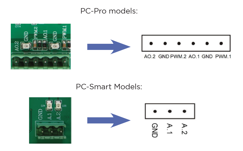
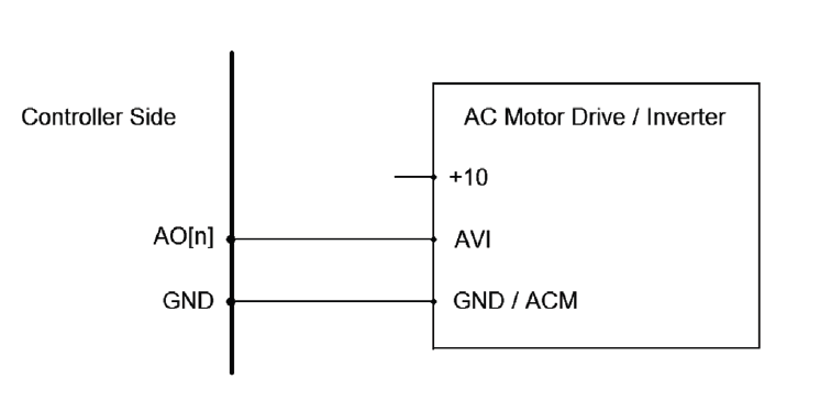
How to connect the analog outputs
4. settings related to spindle
Router\KeepZUp
This variable is used to determine the distance of the Z-axis from the reference point when the machine axes are moved to the reference point. For example, if the entered number is 0.0, the Z-axis will be located at the reference point. If the entered number is 20, the Z-axis will move 20 units in the positive direction from the reference point.
Router\SafeZ
Generally, when moving the axes, the Z-axis is moved to its highest point and after moving the other axes, it moves to the desired point. With this variable, instead of moving the Z-axis to its highest point, it moves up or down from the reference point by the SafeZ value For example, if the highest point of the Z-axis is 0 and the lowest point is 250 and this variable is set to 100, the machine will move the Z-axis 100 units up from the reference point instead of moving it to its highest point.
Router\SpindleAutoOff
This variable is used for GCodes that do not have an M-code to turn off the spindle. The SpindleAutoOff variable is defined as True or False.If this variable is False, SpindleAutoOff is generally disabled and ignored. If this variable is True, SpindleAutoOff is enabled, and at the end of executing the GCode, the spindle is automatically turned off.
Router\SpindleAutoOn
This variable is used for GCodes that do not have an M-code to turn on the spindle. The SpindleAutoOn variable is defined as True or False.If this variable is False, SpindleAutoOn is generally disabled and ignored.If this variable is True, SpindleAutoOn is enabled, and during the execution of the GCode, the spindle is automatically turned on.
Router\SpindleDelay
This variable is used to set the delay time for the spindle to reach the desired speed or stop.The unit for this variable is milliseconds.
Router\SpindleMaxSpeed
This variable is used to determine the maximum speed that can be set for the spindle.
Router\ SpindleMinSpeed
This variable is used to determine the minimum speed that can be set for the spindle.
Router\ SpindleSpeed
This variable is used to store the speed value set for the spindle. For example, if the user sets the Scroll for spindle speed to 18000, the number 18000 is stored in this variable.
Router\SpindleSpeedStep
This variable determines the step change for the SpindleSpeed when using the Scroll. By changing the value of SpindleSpeedStep, the amount of change for each step can be determined. For example, if SpindleSpeedStep is set to 2000, the spindle speed will change by 2000 for each unit of movement in the Scroll.
9. Tool changer
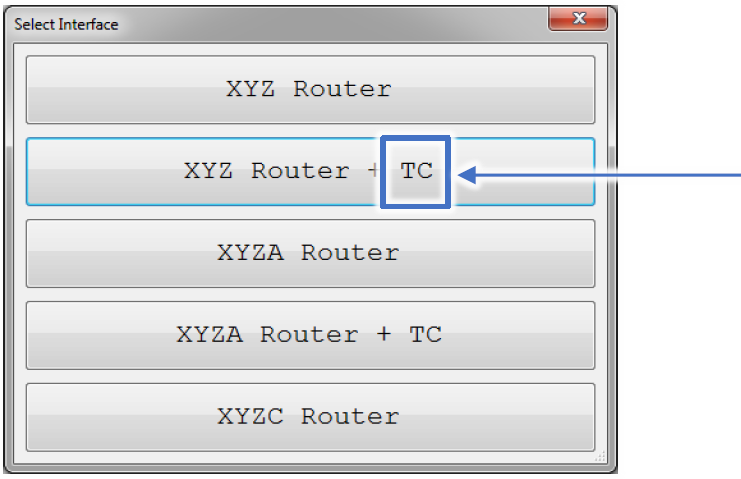
In this section, we will explain the automatic tool change, or Tool Changer, and how to set it up. Initially, depending on the type of axes present in your machine, an interface capable of supporting automatic tool changing should be installed. Interfaces that support automatic tool changing typically have the letters 'TC' at the end of their name.
After installing the interface and opening the Radonix software, the necessary settings for using the Tool Changer must be applied. To do this, first, the Settings window should be opened and the ToolChanger branch, where all the settings related to the Tool Changer exist, should be accessed. In this section, we will explain the essential settings for setting up the Tool Changer.
In the next step, based on the variety of tool changing methods (which are determined based on the type of tool parking on the machine), there are different tool changing options in the Radonix software that the user should choose according to the tool changing method available on their machine. To dothis, go to the Tool Changer branch and the Type variable to determine the type of tool changer on the machine (for more information on the types of tool changing methods, please refer to table number 18 in the Tool Changer branch).
After determining the type of tool changer, we need to set the necessary digital inputs and outputs to issue the essential commands for tool changing. To do this, first go to the System branch and the InPorts sub-branch, and select the desired input. Now, by opening one of the desired inputs, you will encounter three variables for the settings on each of the inputs, which are Enabled, Link, and NC, respectively (for more information on how each of the 3 digital input variables works, pleaserefer to the table in the System branch under the InPorts sub-branch). To perform the tool changing operation, you need 5 inputs, and you should set the links T-ToolHolder,1 (Function link to issue an order to open and close the gripper ), and T-ToolHeightSensorPin (Input link ), T-HSD-S1Pin or (T-ToolSensorPin, T-TEKNO-S2Pin, T-CCS1Pin)(Input link in Table 2), T-HSD-S2Pin or (T-CC-S2Pin, T-TEKNO-S1Pin, T-ToolHolderSensorPin)(Input link in Table 2), and T-HSD-S3Pin or (T-CC-S3Pin, T-TEKNO-S3Pin, T-SpindleRotationSensorPin, T-InverterStopPin) (Input link in Table 2) for them (for more information, please refer to Tables 2 and 4).After that, go to the System branch and the OutPorts sub-branch and select the desired output. Now, by opening one of the desired outputs, you will encounter three variables for setting each of the outputs, which are Enabled, Link, and NC, respectively (for more information on how each of the digital output variables works, please refer to the table in the System branch under the OutPorts subbranch).To perform the tool changing operation, you need 2 outputs, and you should define the links T-ToolHolderPin and T-ToolCleanerPin for them .
After setting up the inputs and outputs, go back to the ToolChanger branch and adjust the remaining essential variables for the tool changing process. (For more information, refer to the ToolChanger table (Table 18) in the ToolChanger branch.)After setting the ToolChanger variables, the coordinates of all the tool parking locations must be determined under the Tools sub-branch in the ToolChanger branch. To do this, first home the machine and then place each tool with its ISO in the desired parking number.
Now, by manually moving or jogging the spindle, it is moved to the position of each tool in the parking area. At this stage, it must be ensured that the gripper is open when the ISO is placed on the spindle (the gripper being open depends on the output that was previously set using the T-ToolHolderPin link (output link in table 3)). A momentary switch connected to the T-ToolHolder,1 digital input link can be used to issue the command, or a virtual button can be added to the software with the same T-ToolHolder,1 link to toggle the output. Now, with great precision, the spindle is brought up to the top of each tool so that the ISO, along with the tool, is fully seated in the tool holder clamps. After that, on the main screen of the software, the Absolute coordinate values of each axis, which indicate the positionrelative to the home point, are entered separately for the coordinates of each parking space, and allparking spaces must be defined in the same way (Figure 24).
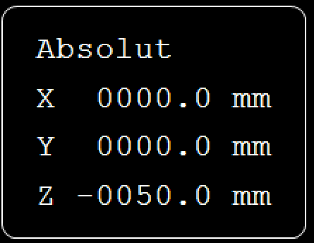
In the final step, the tool height measurement, which is one of the most essential steps in the tool changing process, is performed. In this step, first make sure that the input with the T-ToolHeightSensorPin link (input link in table 2) is defined, and then enter the tool height sensor coordinates in the ToolChanger branch and ToolHeightSensor sub-branch in order of axes (for more information, please refer to the ToolChanger table (table number 18) in the ToolChanger branch).
In summary
In CNC machines with Tool Change (TC) functionality, the tool height reference is not based on the surface of the table; instead, it uses the bottom of the ISO (tool holder base) as the measurement reference. This ensures consistent and accurate tool length measurements.
Steps to Set Tool Height Reference:
-
Tool Reference Parameter:
The Tool Reference parameter acts as the baseline for calculating the tool height. All subsequent tool heights will be measured relative to this value.
-
Entering Parking Coordinates:
After entering the coordinates for all tool parking positions in the software, you need to define the Tool Height Sensor:
- Go to Inputs and assign the input for the sensor as ToolHeightSensorPin.
- Define the sensor's coordinates in its respective section within the ToolChanger branch.
-
Tool Reference Setup:
- First, ensure the tool holder (spindle) is empty. Enter the value 0 in the Tool section on the interface to ensure no tool is currently loaded.
- Manually place an empty ISO tool holder (without any tool) on the spindle.
- Press the Set Tool button.
- The machine will automatically move the tool holder to the Tool Height Sensor.
- The sensor will measure the height of the tool holder and record a value in the Tool Reference parameter.
-
Using the Tool Reference:
The value recorded in the Tool Reference will now serve as the baseline (reference) for all tool height measurements moving forward. Any additional tools loaded will have their heights calculated relative to this baseline.
Simplified Explanation
- Define tool parking positions.
- Configure the ToolHeightSensorPin input and set its coordinates.
- Place an empty tool holder (ISO) in the spindle and press Set Tool.
- The system records the tool holder's position as the Tool Reference.
- This value is the baseline for all subsequent tool height calculations.
+-----------------------------------------+| Start: Automatic Tool Changer Setup |+-----------------------------------------+|V+-----------------------------------------+| 1. Interface Installation | | - Ensure 'TC' support in interface | +-----------------------------------------+ | V +-----------------------------------------+ | 2. Open Radonix Software | | - Access Settings window | | - Navigate to ToolChanger branch | +-----------------------------------------+ | V +-----------------------------------------+ | 3. Set All Inputs and Outputs | | - Configure Digital Inputs: | | * T-ToolHolder,1 | | * T-ToolHeightSensorPin | | * T-HSD-S1Pin ( tool presence sensor) | | * T-HSD-S2Pin ( the spindle clamp sensor which detects the open or closed state of the spindle clamp.) | | * T-HSD-S3Pin ( detecting the rotation of the spindle.) |
+-----------------------------------------+
|V
+-----------------------------------------+| -4. Configure Digital Outputs || * T-ToolHolderPin || * T-ToolCleanerPin || * Refer to Table 4 for settings |+-----------------------------------------+| V +-----------------------------------------+ | 5. Adjust ToolChanger Variables | | - Set remaining essential variables | +-----------------------------------------+ | V +-----------------------------------------+ | 6. Tool Reference Setup | | - Establish the baseline for tool | | height measurement. | | - This reference is crucial as it | | defines the zero or home position | | for the tool height sensor, | | against which all tool lengths | | are measured and calibrated. | | - An empty tool holder or a specific | | calibration tool is placed in the | | spindle, and its position is | | manually set to zero. This sets | | the baseline height for all | | subsequent tool measurements. | +-----------------------------------------+ | V +-----------------------------------------+ | 7. Define Parking Position for Each Tool| | - Manually move spindle to each tool | | - Set and record the parking | | position coordinates for each tool | +-----------------------------------------+ | V +-----------------------------------------+ | 8. Tool Height Measurement Setup | | - Define T-ToolHeightSensorPin input | | - Enter sensor coordinates | +-----------------------------------------+ | V +-----------------------------------------+ | End: Tool Changer Setup Complete | +-----------------------------------------+
All the Inports and Outputs in a glance
-
Home Pins:
- InPort01: HomePin, X
- InPort02: HomePin, Y
- InPort03: HomePin, Z
-
Limit Pins:
- InPort04: LimitPin, X
- InPort05: LimitPin, -X
- InPort06: LimitPin, Y
- InPort07: LimitPin, -Y
- InPort08: LimitPin, Z
- InPort09: LimitPin, -Z
-
Safety and Sensors:
- InPort10: Emergency
Accuracy and References
- InPort11: SurfaceDetectorPin
-
Spindle-Related Pins:
- InPort07: T-ToolHeightSensorPin
- InPort14: T-HSD-S1Pin
- InPort15: T-HSD-S2Pin
- Inport16:T-HSD-S3Pin
- T-ToolHolder,1
Outputs
-
OutPort01: SpindleCWPin (Clockwise spindle control)
-
OutPort03: SpindleCoverPin
-
OutPort04: SpindleCoolerPin
-
OutPort05: T-ToolHolderPin (Tool holder control)
-
OutPort06: T-ToolCleanerPin (Tool cleaner control)
-
OutPort08: BrakePin (Brake control)
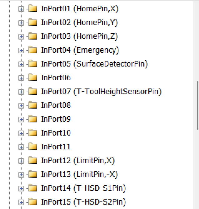
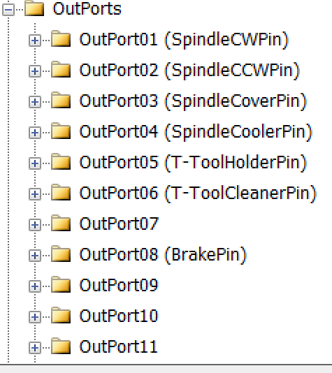
FAQ ( Frequently Asked Questions )
What should I do if my Radonix CNC controller is not showing as online?
Answer: If your Radonix CNC controller is not registering as online, follow these steps to diagnose and resolve the issue:
-
Verify Hardware Connections
- Controller LEDs: Check the LAN connector LEDs on the controller. They should be blinking or on. If they are off, the cable may be disconnected, damaged, or there might be an issue with the connector
- LAN Cable: Ensure the LAN cable is securely connected to both the controller and the computer. Use a CAT5 or CAT6 Ethernet cable, and verify that the length does not exceed 30 meters.
- Power Cycle: Turn off the controller and the computer. Wait for a few minutes before turning them back on. This can resolve minor connectivity issues.
-
Network Settings
Verify that your computer's network settings are configured correctly. Ensure the IP address and subnet mask are appropriately set to match the network settings required by the Radonix controller.
Set the IP address on your computer to communicate with the controller. The default IP address for the controller is
192.168.11.100with a subnet mask of
255.255.255.0Follow these steps:
- Go to Control Panel -> Network and Internet -> Network and Sharing Center -> Change adapter settings.
- Right-click on your network connection and select 'Properties'.
- Select 'Internet Protocol Version 4 (TCP/IPv4)', then 'Properties'.
- Choose 'Use the following IP address' and enter the IP detail Seck Firewall and Antivirus Settings
-
Firewall and Antivirus Configuration
Firewall Settings:
Your controller might not come online if Windows Defender Firewall blocks the Radonix applications. To resolve this:
- Go to Control Panel > System and Security > Windows Defender Firewall > Allow an app through Windows Firewall.
- Unlock settings by clicking "Change settings" in the top-right corner.
- Add Radonix programs (
Radonix CAM Pro,Radonix CAM Pro Test,Radonix CAM Pro Calibrator) to the list if they are missing:- Click "Add an app" and browse to locate the program files.
- Check all network boxes (Private/Public) next to the programs, and save the changes by clicking OK
Antivirus Program Settings:
If you have an antivirus program installed, it might block the Radonix IP or interfere with the network connection. Do not uninstall the antivirus. Instead:
- Open the antivirus settings menu.
- Navigate to the network security or firewall settings within the antivirus program.
- Locate the list of blocked IPs or network connections.
- Remove the Radonix controller IP (
192.168.11.100) from the blocked list, or add it to the list of trusted/allowed IPs. - If there is an option to ignore network checks for specific connections, enable this for the Radonix controller's connection.
- Save your changes and restart the antivirus program to apply the updated settings.
- Firewall and Security Settings: Check if the firewall or antivirus software on your computer is blocking the connection. You may need to configure your firewall to allow traffic from the controller. Refer to your firewall's help guide for instructions on adding exceptions.
Advanced Firewall Settings:
- In some cases, you may need to delete existing Radonix-related rules and start fresh:
- Open Windows Defender Firewall with Advanced Security.
- Navigate to Inbound Rules.
- Find and delete any rules related to Radonix.
- Restart your computer.
- Reconfigure the firewall settings as described above.
- If firewall issues persist, you may need to reset all Radonix-related rules:
- Open Windows Defender Firewall with Advanced Security.
- Navigate to Inbound Rules.
- Locate and remove all Radonix-related rules.
- Restart your computer.
- Set up the firewall rules again using the steps outlined above.
-
Controller Status Lights:
Observe the status lights on the controller. If the LAN LEDs are off, there might be a problem with the network connection. or a controller may face an internal hardware issue .
-
Software Configuration:
Open the Radonix software and check the Connection status in Setting —→ System —→Connection = LAN
-
Consult the Manual:
Refer to the troubleshooting section of the Radonix CNC controller manual to recheck all settings by Images for more details.
-
Technical Support:
If the above steps do not resolve the problem, contact Radonix support for further assistance. Provide them with details of the steps you’ve already taken and any error messages or codes displayed.
Resolving Home Pin Issues and Direction Settings:
In some cases, customers report that even after setting all Home Pin parameters, the machine does not operate correctly. One common issue occurs when the operator presses the Home button, and the axis moves in the opposite direction. This indicates that the direction setting needs to be adjusted. It is crucial to align direction settings with standard practices (for detailed guidance, refer to the Radonix Book, Page 52).
After confirming the proper direction of movement, two key parameters must be addressed:
- Movement Direction: The direction in which an axis moves during operation.
- Home Direction: The direction the axis takes when the Home button is pressed.
To configure these parameters:
- Navigate to:
Settings > Systems > Axis 1,2,3,... / Direction. - Select the appropriate option:
PositiveorNegative.
Defining Max and Min Course Values
Each axis requires defined Max Course and Min Course values to establish its operating range. For example:
- On an X-axis with a 2-meter table length:
- Set Max Course to
2000 mm. - Set Min Course to
0 mm.
- Set Max Course to
- On a Z-axis with a downward range of -200 mm:
- Set Max Course to
0 mm. - Set Min Course to
200 mm.
- Set Max Course to
The concept of positive and negative direction is inherently tied to the Max Course and Min Course values. Movement toward the Max Course is considered positive, while movement toward the Min Course is considered negative.
In the context of homing, the Home direction becomes predictable based on these definitions. When the operator presses the Home button, the axis moves to locate the home sensor. If the Home Direction is set to positive, the axis will travel toward the Max Course to detect the home sensor at the maximum end. Conversely, if the Home Direction is set to negative, the axis will travel toward the Min Course to detect the home sensor at the minimum end.
This setup ensures that positive movement aligns with increasing values toward the Max Course, while negative movement aligns with decreasing values toward the Min Course.
Home Direction
When the Home button is pressed, the axis moves toward the Home sensor. The Home direction is determined by the set Home Direction:
- If set to
Positive, the axis moves toward the Max Course to locate the Home sensor at the maximum end. - If set to
Negative, the axis moves toward the Min Course to locate the Home sensor at the minimum end.
By aligning these settings with the machine's physical parameters and ensuring they match the Home sensor's location, operators can ensure smooth and accurate homing operations.
Passes the sensors without triggering them
Possible Causes and Solutions
Wiring sensors and connecting them to the inputs is a critical process in ensuring the proper operation of Radonix CNC systems. Typically, sensors have three wires: two for power supply and one for output, which connects to the input ports of the Radonix controller.
The input ports of Radonix controllers can operate in two modes: NPN (Zero Volt or Sink) and PNP (24 Volt or Source). The mode determines how the input pins are triggered, and it directly depends on how the inputs are wired.
Mode Configuration Using the COM Pins
In Radonix PC Smart series, the mode selection for input ports is achieved via the COM pins on the board. These pins play a crucial role in defining the input mode:
- PNP Mode (Source Mode):
- If the COM pin is connected to 0V, the input pins will be triggered (turned ON) by a 24V signal.
- In this configuration, the sensor’s output wire must provide a 24V signal to activate the input.
- NPN Mode (Sink Mode):
-
If the COM pin is connected to 24V, the input pins will be triggered (turned ON) by a 0V signal.
-
In this configuration, the sensor’s output wire must pull the input to 0V to activate it.
Wiring Sensors:- Power Wires: Two wires from the sensor should be connected to the power supply (usually 24V and 0V, depending on the sensor specification).
- Output Wire: The output wire of the sensor should be connected to the appropriate input port on the Radonix board. The behavior of this connection depends on the selected mode (PNP or NPN) and the wiring of the COM pin.
Best Practices:- Verify Sensor Type: Confirm whether the sensor is compatible with NPN, PNP, or both modes.
- Follow the Sensor Manual: Ensure the wiring complies with the sensor manufacturer’s guidelines.
- Secure Connections: Make sure all connections are tight and free from interference or cross-wiring.
- Test Functionality: After wiring, test the sensor outputs by manually triggering them and monitoring the corresponding inputs on the controller.
By carefully following these steps and guidelines, the sensors will function reliably, and the CNC system will operate with optimal performance. Proper wiring also minimizes potential errors or faults in the system.
-
hardware issues
Software issues
If the axis passes the sensors without triggering them, it indicates an issue with the configuration or wiring of the sensors and inputs. This reaction typically happens due to one of the following reasons
Faulty Sensor
Testing and Verifying Inputs in Radonix CAM Test Environment
Every part and component of the system can be checked in a controlled test environment. A comprehensive guide for setting up the test environment is available in the Radonix Book, Page 185. Specifically, the input section relevant to testing issues like sensor functionality can be evaluated through this process.
Using CAM Test Application for Input Verification
- Accessing CAM Test:
- Open the CAM Test application, which is automatically installed within the CAM Pro software package.
- Note: Ensure that only one Radonix application is running at a time. If multiple Radonix applications are opened simultaneously, one of them will fail to function properly.
- Observing Inputs in CAM Test:
- The CAM Test interface provides real-time status updates for all inputs.
- For example, as shown in the provided image, Input 4 and Input 5 are triggered and highlighted as active (turned on). This indicates that the sensors connected to these inputs are operational.
- Testing Procedure:
- Position a metal object in front of the sensors. The corresponding inputs in the CAM Test interface should light up, confirming that the sensors are detecting the object and sending signals to the controller.
- If an input does not activate when the sensor is triggered, check the following:
- Wiring connections to ensure proper configuration.
- COM pin settings for the appropriate sensor mode (PNP or NPN).
- Sensor alignment and placement.
- Input assignments in the Radonix software settings.
- Interpreting the Results:
- If the inputs are highlighted as active when a sensor is triggered, it confirms that the sensors are correctly wired, positioned, and functional.
- If the inputs remain inactive, review the sensor configuration, test the sensor independently, and ensure that the input pins are correctly mapped in the software.
By using the CAM Test application in this manner, operators can efficiently diagnose and verify sensor functionality and address any issues related to input configuration or wiring. This ensures smooth operation of the CNC system and minimizes downtime.
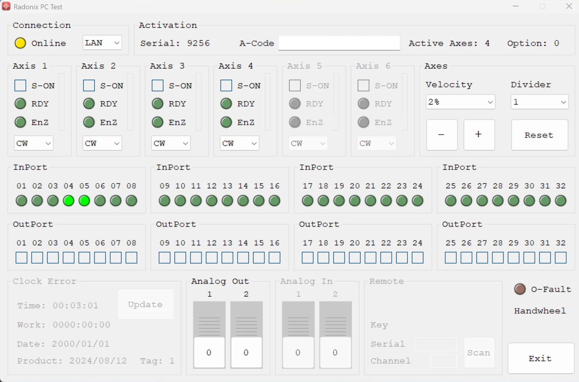
- Test the sensor independently to ensure it is functioning correctly. You can do this by manually placing an object in front of the sensor and checking its output signal.
Being Normally Open or Close
Normally Open (NO)
- In a normally open circuit, the circuit is disconnected (open) by default.
- When a trigger or an activation signal occurs (e.g., pressing a button or activating a sensor), the circuit closes and allows the current to flow.
Example:
- A doorbell switch is a normally open circuit. When you press the button, the circuit closes, and the bell rings.
Normally Closed (NC)
- In a normally closed circuit, the circuit is connected (closed) by default, allowing current to flow.
- When a trigger or an activation signal occurs, the circuit opens, stopping the current flow.
Example:
- An emergency stop button is a normally closed circuit. Pressing the button opens the circuit, stopping the machine.
Parameter for NC (Normally Closed)
In each sub-branch of inputs:
- After setting
Enabledto true and establishing the link (connecting the input to a specific function or trigger), you will encounter a parameter that determines the circuit behavior as Normally Open (NO) or Normally Closed (NC). - This parameter is often labeled as
NC(Normally Closed).- If
NCis set to true, the input behaves as Normally Closed by default. This means the circuit remains closed (active) until a trigger causes it to open. - If
NCis set to false, the input behaves as Normally Open by default. This means the circuit remains open (inactive) until a trigger causes it to close.
- If
Practical Usage
- Normally Open (NC = false):
- Use when the circuit is meant to remain off or inactive by default.
- Example: A sensor that activates only when an object is detected (e.g., proximity sensors in automation).
- Normally Closed (NC = true):
- Use when the circuit is required to remain on or active by default for safety or monitoring purposes.
- Example: Emergency stop buttons or safety interlocks that disconnect power when triggered.
Why This Parameter Matters
- It allows flexibility to match the input behaviour to the physical configuration of your sensors, switches, or devices.
- Ensures compatibility with both safety-critical and functional requirements in a system.
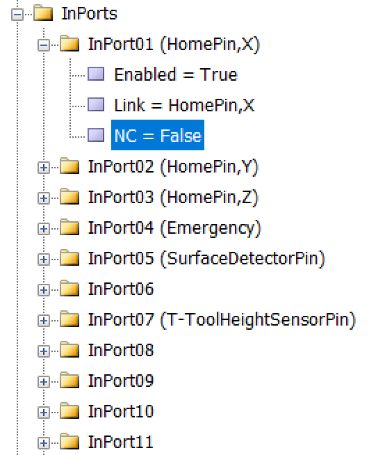
In some cases, installers incorrectly set the normally closed configuration, which results in the axis not stopping after passing the sensor
How can we are able to increase or decrease velocity ?
Electronic Gear Box (E-Gear) Considerations
Before making any adjustments to the system, it is essential to thoroughly understand the role and configuration of the Electronic Gear Box (E-Gear). This parameter is crucial for ensuring your motor receives the appropriate number of pulses to achieve the desired performance, including reaching its maximum rotation per minute (RPM).
To properly configure the Electronic Gear Box (E-Gear) and achieve optimal performance from your CNC machine, further insights can be drawn from the Calibration section. The calibration process not only ensures accurate motion control but also plays a crucial role in verifying that the E-Gear settings are aligned with your motor and encoder requirements.
Adjusting Velocity in Radonix Systems
Radonix controllers are designed with diverse parameters to allow precise velocity adjustments tailored to various aspects of a CNC machine’s movement. When configuring velocity settings, it’s essential to consider the specific part of the motion you intend to adjust. Understanding the context of the movement ensures optimal performance, accuracy, and efficiency.
Key Velocity Adjustment Parameters
1. Traverse Velocity:
- Controls the speed during non-cutting movements, such as when the machine moves between different positions.
- Ensures efficiency by enabling rapid travel without compromising safety or mechanical integrity.
- Location: This setting is found under
System\ToolPath\TraverseVelocity. - Purpose: It determines the axis displacement speed when moving without executing a specific cutting program (i.e., during rapid movements using G0 command).
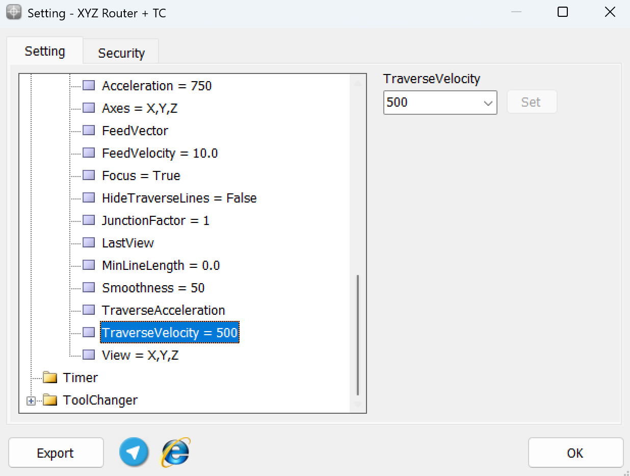
2. Feed Velocity:
- Defines the speed at which the tool moves during actual machining operations (e.g., cutting, engraving, or milling).
- When the Feed or F value is not defined in the G-Code, the value specified in this variable is used as the basis forthe movement speed.
- Critical for achieving the desired surface finish, precision, and machining quality.
- Location: Located under
System\ToolPath\FeedVelocity. - Purpose: Used when the feed rate (F value) is not specified in the G-Code. This setting acts as the default movement speed during program execution.
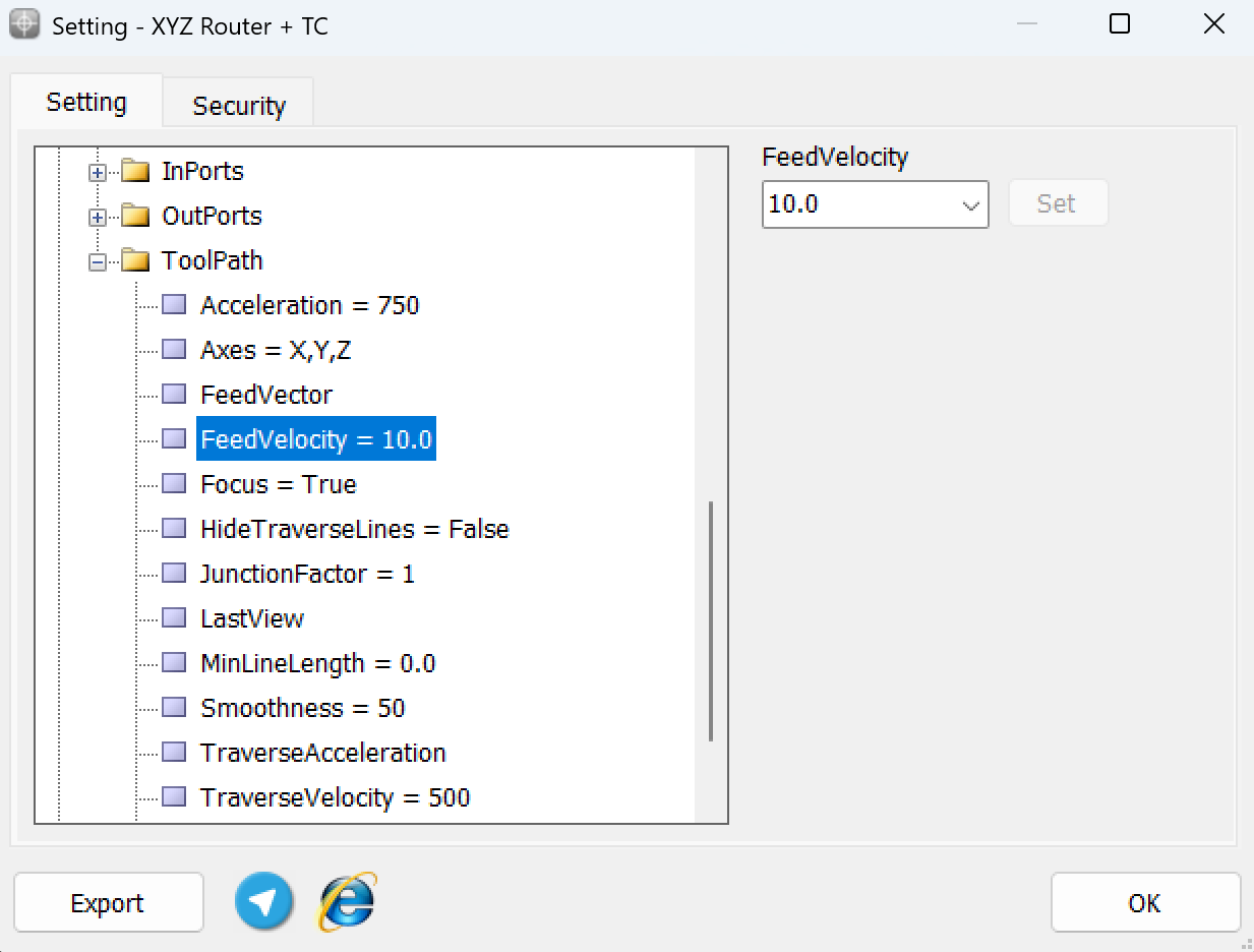
3. Home Return Velocity:
- Adjusts the speed at which the machine returns to its Home position during the homing cycle.
- Set at a moderate speed to prevent collisions or inaccuracies during initialization.
- Location: Accessible via
System\Axes\Axes"N"\HomeVelocity. - Purpose: Sets the velocity at which the machine axes return to the home position during homing operations.
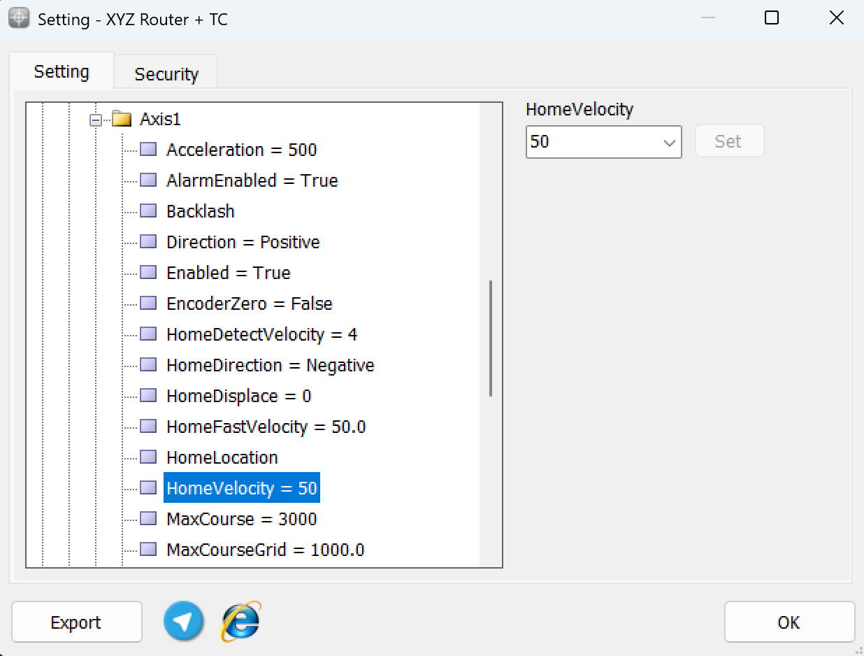
4. Jog Velocity:
- Sets the speed for manual control of the machine’s axes during jogging operations.
- Used for precise positioning or fine adjustments before executing a program.
- Location: Found in
System\General\Axes"N"\JogVelocity. - Purpose: This parameter adjusts the speed for manual jogging of the machine axes, allowing operators to control the pace at which axes move when controlled manually via jog commands.
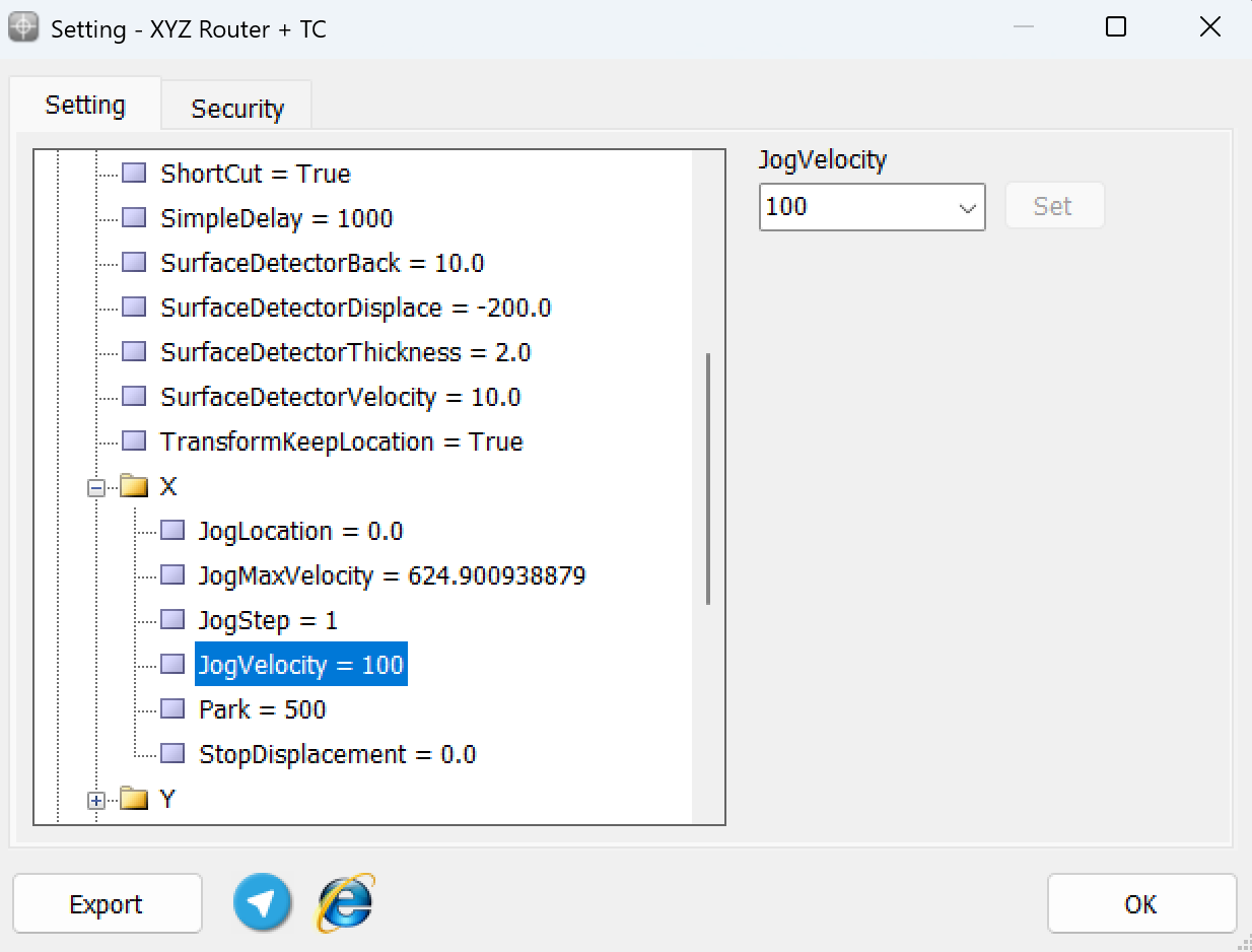
5. ToolPath Acceleration:
- Determines the acceleration of all axes simultaneously during program execution.
- Optimized based on factors like inertia, axis weight, and motor power, ensuring smooth multi-axis movement.
- Location: The settings for toolpath acceleration can be found under
System\ToolPath\Acceleration.
Setting Details: This variable is used to determine the acceleration of the axes simultaneously during program execution, measured in units per second squared (unit/s²). The appropriate values for this setting are calculated based on mechanical factors like inertia, axis weight, and motor power. Generally, there's an inverse relationship between the inertia and axis weight, and a direct relationship between motor power and the acceleration value.
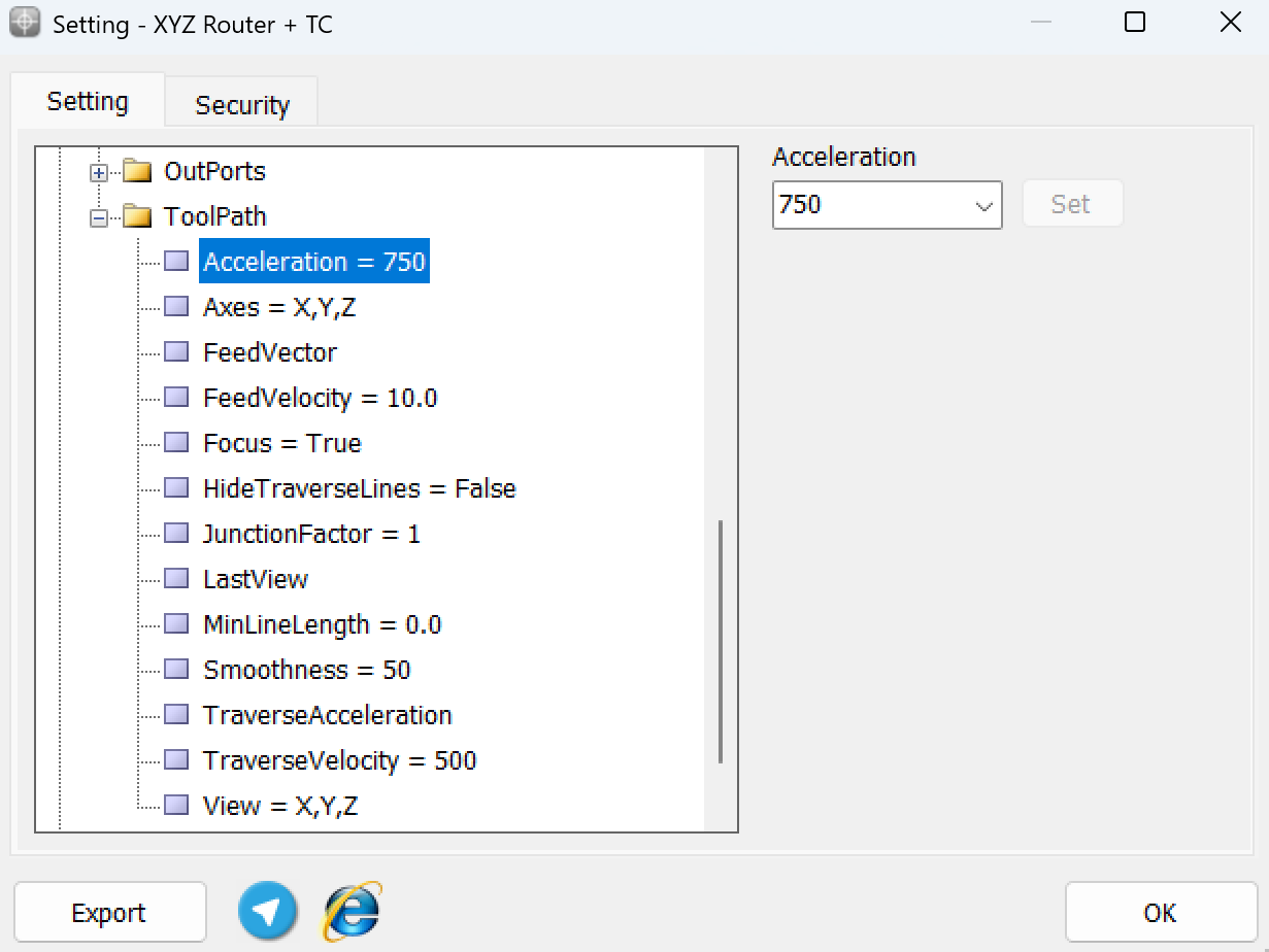
6. Axes[n] Acceleration:
- Controls the acceleration for individual axes independently.
- Allows fine-tuning for each axis based on its specific characteristics, such as stiffness, weight, and motor power.
- Location: Found under
System\Axes\Axes"N"\Acceleration. - Description: This setting allows you to define the acceleration rate for each individual axis, where "N" is the identifier number between 1 to 6, representing the axis number. This variable specifies how quickly an axis can increase its speed from a standstill to its designated velocity, measured in units per second squared (units/s²).
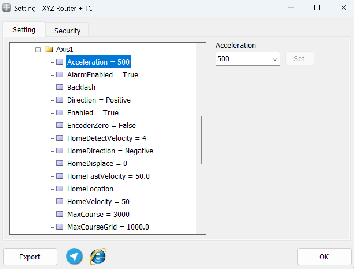
Best Practices for Velocity Adjustment
- Identify the Purpose: Clearly determine which aspect of movement you want to adjust before modifying any parameters.
- Example: For faster setup, focus on Rapid Travel Velocity. For smoother machining, adjust Cutting Velocity.
- Consider the Machine’s Capabilities: Ensure that the velocity values do not exceed the mechanical or operational limits of your CNC machine to avoid wear or damage.
- Test and Optimize: After adjusting velocity settings, perform test runs to validate performance and make fine adjustments as needed.
- Review Interdependencies: Some parameters, such as acceleration, directly affect velocity settings. Ensure a balanced configuration for optimal results.
Something goes wrong !!! … motors don’t move!?
When motors don’t move, there are several factors to consider—particularly matching the board type (PC-Smart or PC-Pro LAN) with the motor type (stepper or servo) and ensuring your pulse settings, jog speeds, and alarm states are properly configured. Follow these steps:
1- Identify Your Controller Board and Motor Type
-
PC-Smart or PC-Pro LAN (4Axis or 6Axis)
-
These boards can output up to 500,000 pulses per second.
-
If you’re using stepper motors on a 4Axis or 6Axis board:
-
You must set a suitable pulse division on your stepper driver, use pulse division like 1/5 pulse or 1/10 pulses .
The Pulse divider is located in Setting —->System —>PulseDivder
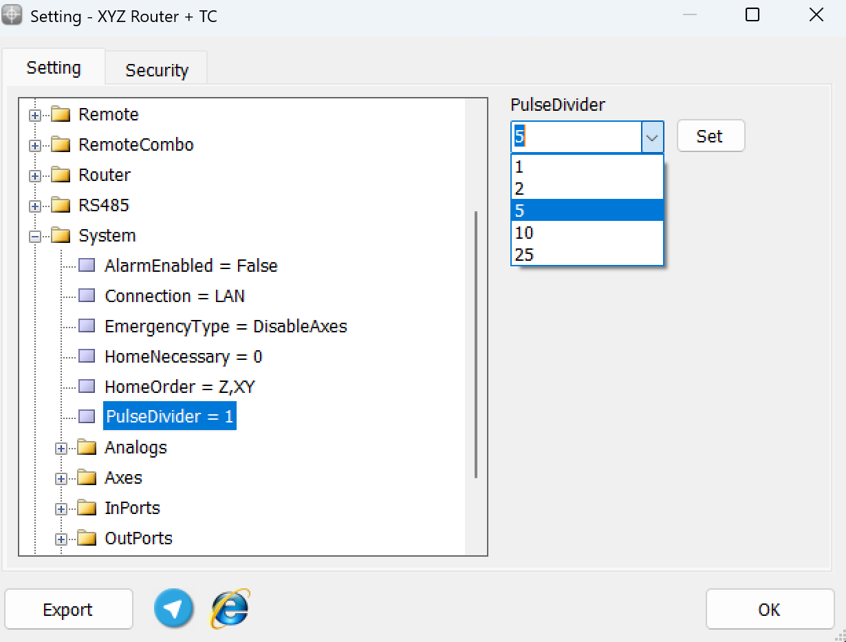
- If the division is too high or too low, the motors may receive too many or too few pulses, preventing motion.
-
-
If you’re using servo motors on a 4Axis or 6Axis board:
- Do not divide the pulses in the servo driver. Servos typically accept the full pulse rate directly.
PC-Smart 3AS
- Designed specifically for stepper motors in terms of pulse or the number of digital input or digital output with a different maximum pulse rate (100,000 PPS ).
- Do not apply additional pulse division if you’re using the 3AS board with standard stepper drivers; use the drivers’ default recommended settings for micro-stepping.
-
2- Confirm Wiring & Basic Requirements
- The axis cable carries critical signals (pulse, direction, alarm, ready, etc.) between the controller and the motor driver.
- A loose, bent, or incorrectly seated pin can disrupt these signals, causing the motor to fail to move or behave erratically.
- Check that power supply voltage is correct and cables are securely attached to drivers and motors
3- Set Appropriate Jog Speeds in Radonix CAM-Pro
- In Radonix CAM-Pro, each axis has a Velocity value on the surface . Sometimes it turned to 0.1 or become a low value so in fact it has movement but its sow slow and its not detecatable
- Reduce the jog speed to a modest value (e.g., 10 mm/s) and see if the motor responds
4- Check for Alarms on Servo Drivers
- If you’re using servo motors:
- The servo driver itself may be in an Alarm state due to a fault (e.g., overcurrent, encoder error).
- View the Report Section in Radonix CAM-Pro to see if any alarm codes are displayed.
- Cross-reference those codes with the servo driver’s user manual to identify the cause.
5- Disable Alarms When Using Steppers on 4Axis/6Axis
If you have STEPPER MOTORS on a 4Axis or 6Axis controller board:
- Disable the “Alarm Enabled” parameter for each axis in the Settings section (found in Setting → Setting → System →Axis ).
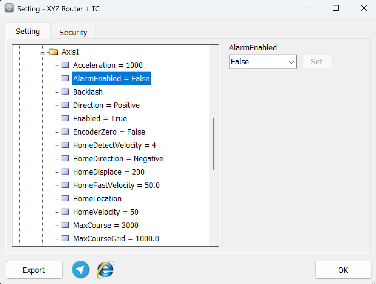
2.Disable the main “Alarm Enabled” option in Setting → System.
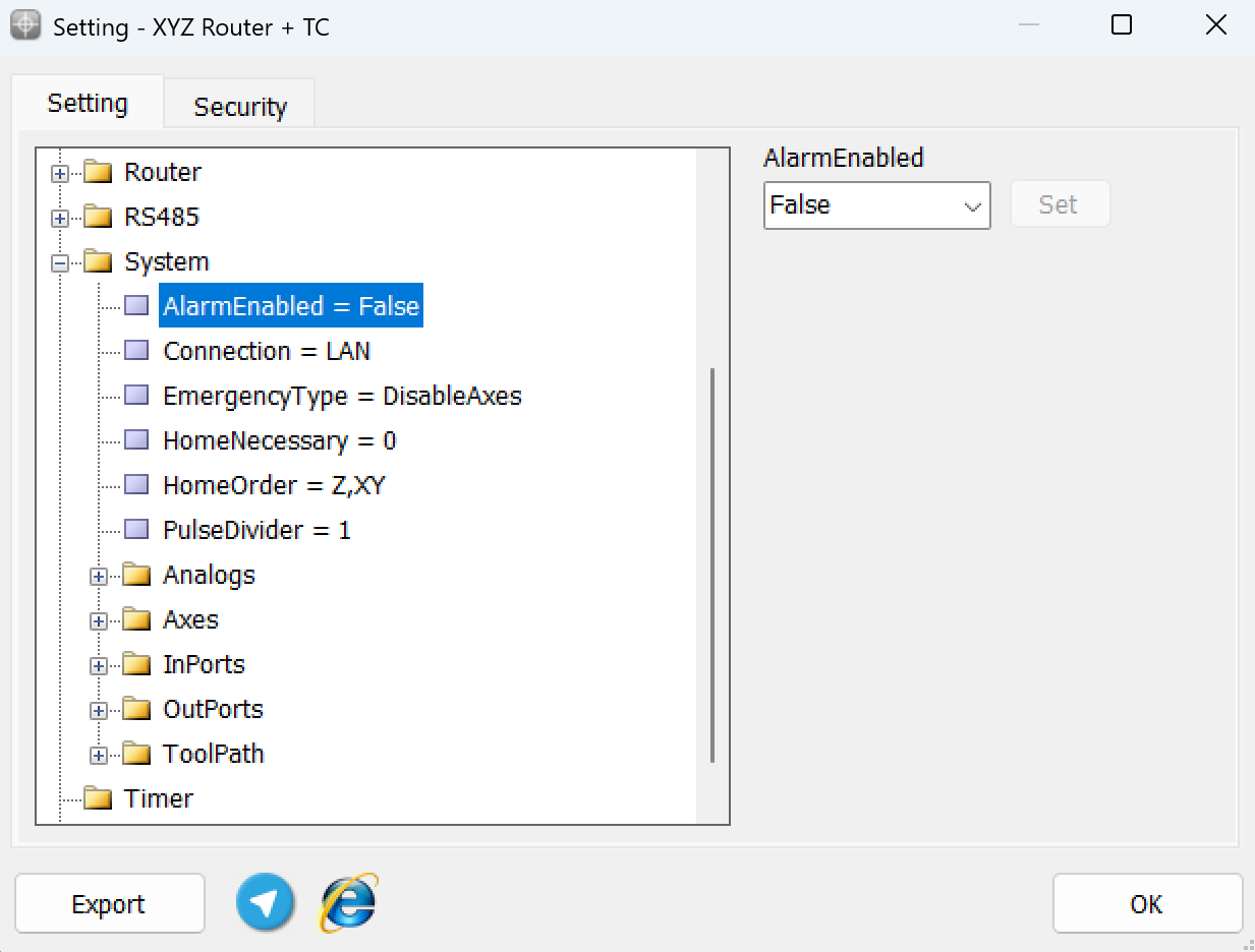
3.Close and re-open Radonix CAM-Pro for the changes to take effect.
6- Other Common Checks
Limit Switches & E-Stop:
- Ensure the machine isn’t on a triggered limit switch, and the emergency stop is disengaged.
Online vs. Offline:
- Verify the controller is “Online” in the software (LAN cable plugged in, correct IP settings).
Tool changing faces a problem it stopped during tool change process
Troubleshooting Tool Change Issues
Issue Description:
During tool changes, the spindle correctly places a tool in its parking spot but then stops and fails to retrieve the next tool. This section guides you through a method to diagnose and potentially resolve this issue.
Caution:
Disabling spindle sensors is a diagnostic step that bypasses built-in safety features. Exercise extreme caution when performing these steps, and ensure all other safety protocols are strictly followed to prevent accidents.
Step-by-Step Troubleshooting Guide
- Identify the Problem:
- If the spindle parks the tool but does not proceed to pick up the next tool, there may be an issue with one or more of the spindle's sensors.
- Disable Spindle Sensors:
-
Temporarily disable the sensors associated with the spindle. These typically include sensors labeled THSD-S1, THSD-S2, and THSD-S3.
-
Navigate to the sensor settings in the Radonix CAM-Pro software:
Copy code Settings > System > InPorts > Disable THSD-S1, S2, S3 -
Note: Disabling these sensors removes safety checks during tool changes.
-
- Test Tool Change:
- With the sensors disabled, issue a command to initiate a tool change cycle.
- Observe whether the spindle can now successfully pick up the next tool without stopping.
- Example Command:
T1 M6(Change to tool 1)- Observe if the spindle retrieves tool 1 successfully.
- Analyze the Results:
- If the tool change succeeds without any issues, it suggests a sensor malfunction.
- If the spindle still fails to pick up the next tool, the issue might be related to other mechanical or software settings.
- Identify the Faulty Sensor:
- Reactivate each sensor one at a time and test the tool change procedure after each activation.
- Enable THSD-S1 and test.
- If no issues, enable THSD-S2 and test, and so on.
- This step helps pinpoint which sensor is causing the problem.
- Reactivate each sensor one at a time and test the tool change procedure after each activation.
- Final Checks:
- Once the problematic sensor is identified, check for:
- Loose connections or wiring.
- Physical blockages or alignment issues.
- Sensor damage or wear.
- Once the problematic sensor is identified, check for:
- Reactivate All Sensors:
- After troubleshooting, ensure all sensors are reactivated to restore safety features:
- Test the tool change operation again to confirm functionality with all sensors active.
Additional Recommendations
- Regular Maintenance: Regularly inspect and maintain all spindle sensors to avoid similar issues.
- Consult Technical Support: If you cannot resolve the issue, contact Radonix technical support for further assistance.
Summary
This guide provides a methodical approach to diagnosing and fixing tool change issues related to spindle sensors in Radonix CNC systems. Remember, the safety of your operations should never be compromised. Always ensure that all safety sensors are functioning correctly after any troubleshooting or maintenance.
You have Emergency or Alarm sign
Troubleshooting Guide: Machine Cease Operation
Issue Description:
If your CNC machine has stopped unexpectedly and fails to home, you might encounter "Alarm" and "Emergency" indicators. These warnings are critical signals that the machine has identified a fault or safety concern.

Initial Steps
- Ensure Machine is Online:
- Verify that the CNC machine is connected and communicative with the control software. Being online is crucial to access diagnostic tools and error reports.
- Check Control Panel:
- Examine the control panel or interface for immediate visible alerts such as red warning lights or error messages displayed directly on the machine.
Detailed Diagnostic Procedure
- Access Report Section:
- Navigate to the report section in your CNC control software. This section aggregates and displays all operational alarms and system messages.
- Look for any entries marked as "Alarm" or "Emergency". These entries can provide clues about the nature of the problem.
- Identify Alarms:
- Alarms typically indicate specific faults in the machine’s operation, such as overloads, faults in the electrical system, or mechanical failures.
- Each alarm code or message will correspond to a specific issue, detailed in your machine's user manual. Refer to this document to understand what each alarm code means.
- Emergency Stop (E-Stop) Status:
- Check if the emergency stop button is engaged. An engaged E-Stop will halt all machine operations and must be reset before operations can continue.
- Reset the E-Stop by pulling or twisting it as required, then on the control interface, acknowledge or clear the emergency state.
- Diagnose with Live Monitoring:
- If the system is online and alarms are active, use live diagnostic tools provided in your software to monitor machine status in real time.
- Look for irregularities in machine behaviour, such as unexpected axis movements, abnormal sounds, or other indicators of mechanical distress.
- Check Connection and Sensors:
- Inspect physical connections for looseness or damage, especially wiring to sensors that might trigger alarms if disconnected or malfunctioning.
- Verify sensor feedback in the software to ensure all sensors are operational and correctly reporting status.
Actions Post-Diagnostics
- Resolve Alarms:
- Address each identified issue based on the alarm codes and the user manual’s troubleshooting section.
- Replace or repair any faulty components as indicated by the diagnostics.
- Test Machine Functionality:
- Once alarms are cleared and the emergency state is reset, conduct a test run starting with simple movements to ensure the machine is functioning correctly.
- If possible, perform a dry run without cutting material to verify that all operations return to normal.
- Documentation and Follow-Up:
- Document the incident, noting the alarms encountered, the diagnostics performed, and any repairs or replacements made.
- If the issue recurs or if initial diagnostics do not resolve the problem, consider contacting technical support for further assistance.
Summary
When a CNC machine ceases operation and fails to home, promptly checking for alarms and emergency indicators in the control software is crucial. By methodically diagnosing and resolving these alerts, you can safely return your machine to normal operation while ensuring all safety measures are observed.
How can use LimitPin as a HomePin too?
Configuring Limit Switches as Home Switches
Overview:
Using limit switches as home switches is a common requirement that can simplify wiring and configuration by combining two functionalities into a single input. This configuration ensures that the limit switch not only controls the axis limits but also sets the home position.
Configuration Steps:
- Identify the Limit Switch Input:
- Determine which limit switch you want to use as the home switch. This switch must be capable of detecting the end or home position of an axis reliably.
- Input Configuration:
- Configure the input in the control software to recognize the limit switch as both a limit and home position indicator.
- Syntax for Setting the Input:
-
Positive Direction Home Setting:
Copy code LimitPin, AxisName, H- Description: This setting configures the limit switch input for an axis to serve as the home position indicator when moving in the positive direction.
- AxisName: Replace
AxisNamewith the actual axis label (X, Y, Z, A, B, C) depending on which axis you are configuring.
-
Negative Direction Home Setting:
Copy code LimitPin, -AxisName, H- Description: Similar to the positive direction, but used for configuring the switch as the home position in the negative direction of the axis.
- AxisName: Replace
AxisNamewith the negative axis label (-X, -Y, -Z, -A, -B, -C).
-
How can i set multi reference on interface?
Setting Multiple Reference Points in Radonix CAM-Pro
Overview
Multiple reference points are used to store and recall specific positions on a CNC machine, facilitating operations on different areas of a workpiece or for jobs requiring precise repositioning.
Stage 1: Enable Multi-Reference Setting
- Navigate to Settings:
- Open the Radonix CAM-Pro software.
- Go to the Settings menu, then locate the G-code branch.
- Activate Multi-Reference:
- Find the setting for Multi Reference.
- Set it to True to enable the use of multiple reference points.
Stage 2: Enter Edition Mode
- Access Edition Mode:
- Press Alt + Ctrl + Shift + Home on your keyboard to enter Edition Mode.
- Note: On some keyboards, the Fn key may also need to be involved to activate the Home key.
- Press Alt + Ctrl + Shift + Home on your keyboard to enter Edition Mode.
Stage 3: Configure Reference Buttons in Edition Mode
- Add Reference Buttons:
- Right-click on an empty space in the on the interface where you want the reference buttons.
- Select Add Button from the context menu to create a new button.
- Repeat this process to add as many buttons as you need, depending on how many reference points you require.
- Set Button Properties:
- Right-click on the newly created button.
- Choose Properties from the context menu to open the button properties window.
- Link Buttons to References:
- In the Properties window, navigate to the Link section.
- Enter the link commands for setting up references:
- Select reference,54 for the first reference button.
- Select reference,55 for the second.
- Select reference,56 for the third.
- Optionally, set a custom text for each button that describes its reference position.
- Exit Edition Mode:
- Once all buttons are configured, exit Edition Mode to save your changes and return to normal operation mode.
Using Reference Points
- Select a Reference Button:
- Choose the desired reference button to activate that specific reference setting.
- Move to Desired Location:
- Manually move the CNC machine to the location you want to save as a reference point.
- Save the Position:
- Press the reference button like X0 / Y0/ Z0 corresponding to each axis to save that position. Repeat for each reference needed.
- Recall a Reference:
-
To use a saved reference point, select the corresponding button and issue a command to move to that reference. The machine will move to the saved start point.

-
Summary
Setting multiple reference points allows you to efficiently manage various starting positions for different tasks or parts of a workpiece. By following these steps, you can configure and utilize up to three reference points in Radonix CAM-Pro, enhancing your operational flexibility and precision. Always ensure you are familiar with navigating the software and understanding the implications of changing reference points to avoid operational errors.
How can I run G-Code with out Home processes .
The "Home Necessary" setting in Radonix CAM-Pro controls whether the CNC machine requires homing before operations can begin. Adjusting this setting accommodates different operational needs and safety protocols.
Accessing Home Necessary Setting:
- Open Radonix CAM-Pro:
- Launch the Radonix CAM-Pro software on your system.
- Navigate to System Settings:
- Go to: Settings > System to access system-level options.
- Locate Home Necessary:
- Find the Home Necessary option within the system settings. This setting determines the operational requirements regarding the machine's home position.
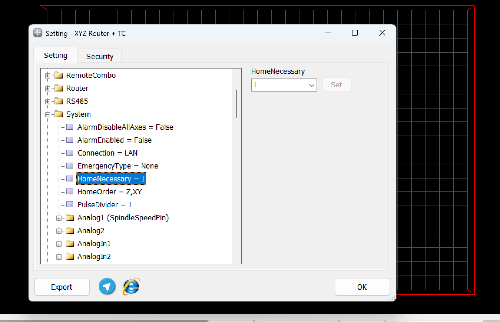
Settings and Their Implications:
-
Home Necessary = 0
- Description: The home position of the machine is not required for operation.
- Implications:
- Axes movement: Both axes can be moved manually without having homed the machine.
- Program execution: G-code programs can be executed regardless of whether the machine has been homed.
-
Home Necessary = 1
- Description: The home position is not strictly required, but has implications for G-code execution.
- Implications:
- Axes movement: Manual movement of the axes is permitted without homing.
- Program execution: G-code programs cannot be executed unless the machine has been homed first.
-
Home Necessary = 2
- Description: The machine must be homed before any manual or programmed operations can take place.
- Implications:
- Axes movement: Neither axis can be moved manually unless the machine has first been homed.
- Program execution: G-code cannot be executed unless the machine is in a homed state.
Test Carefully:- Run the machine at a slower feed rate to ensure the G-code behaves as expected.
- Keep an eye on the emergency stop button in case the machine attempts to move outside its physical boundaries.
When Should You Skip Homing?- Prototyping or quick tests where precision isn't critical.
- Machines without limit switches or homing sensors.
However, skipping homing can lead to inaccurate machining if the machine loses its position. Ensure the setup and environment are controlled to avoid damage or misalignment.
I need to change the Home Order (alter the origin or home axis). How should I do this?
Overview:
The Home Order setting in Radonix CAM-Pro allows users to specify the order and manner in which the CNC machine's axes are homed. This flexibility is crucial for ensuring that the homing process adheres to machine-specific requirements and safety protocols.
Accessing Home Order Settings:
- Navigate to System Settings:
- Open Radonix CAM-Pro.
- Go to Settings > System to access the system configuration options.
- Locate Home Order:
- Find the Home Order setting within the system settings. This setting determines the sequence and method of axis homing.
Configuring Home Order:
- Sequential Homing (with commas):
- Format:
Axis1, Axis2, Axis3 - Description: Axes listed with commas are homed one after another in the order specified.
- Example:
Z, X, Y- The Z-axis is homed first.
- After the Z-axis is fully homed, the X-axis is homed next.
- Finally, the Y-axis is homed after the X-axis.
- Format:
- Simultaneous Homing (no commas):
- Format:
Axis1Axis2Axis3 - Description: Axes listed without commas are homed simultaneously.
- Example:
ZXY- The Z, X, and Y axes are homed at the same time, ensuring that all axes reach their home positions concurrently.
- Format:
Use Cases and Recommendations:
- Z Before XY (Sequential):
- Configuration:
Z,XY - Rationale: Homing the Z-axis first prevents potential crashes by ensuring that the tool is clear of any workpiece or clamping devices before the X and Y axes move.
- This configuration is typical for machines where vertical clearance is a safety and operational concern.
- Configuration:
- Fully Sequential Homing:
- Configuration:
Z,X,Y - Rationale: Fully sequential homing provides the highest level of control, reducing the risk of mechanical interference between axes, especially useful in complex setups or when precise calibration is needed after maintenance or part replacements.
- Configuration:
- Simultaneous Homing:
- Configuration:
ZXY - Rationale: Simultaneous homing can be faster and is often suitable for machines designed with interdependent axis mechanics where simultaneous movement does not risk crashes or overloads.
- Configuration:
Best Practices:
- Safety First: Always ensure that the homing sequence respects the physical constraints and safety features of the CNC machine. Avoid configurations that might lead to axis collisions or undue stress on mechanical components.
- Documentation: Document any changes to the Home Order setting in operational logs or machine manuals. Ensure all operators are aware of the current configuration.
- Regular Review and Testing: Regularly review and test the homing sequence, especially after any mechanical adjustments, to ensure that the settings remain optimal and safe.
Summary:
The Home Order setting in Radonix CAM-Pro is designed to provide operators with the ability to tailor the axis homing sequence to the specific needs and configuration of their CNC machine. Whether choosing sequential or simultaneous homing, operators can optimize the process for efficiency, safety, and precision. Adjust this setting according to your machine's specifications and operational requirements.
When I play G-Code at first it goes to reference G-54 then goes to cut or executable G-code so it takes time.
Go to —→ Setting / General / Shortcut = True
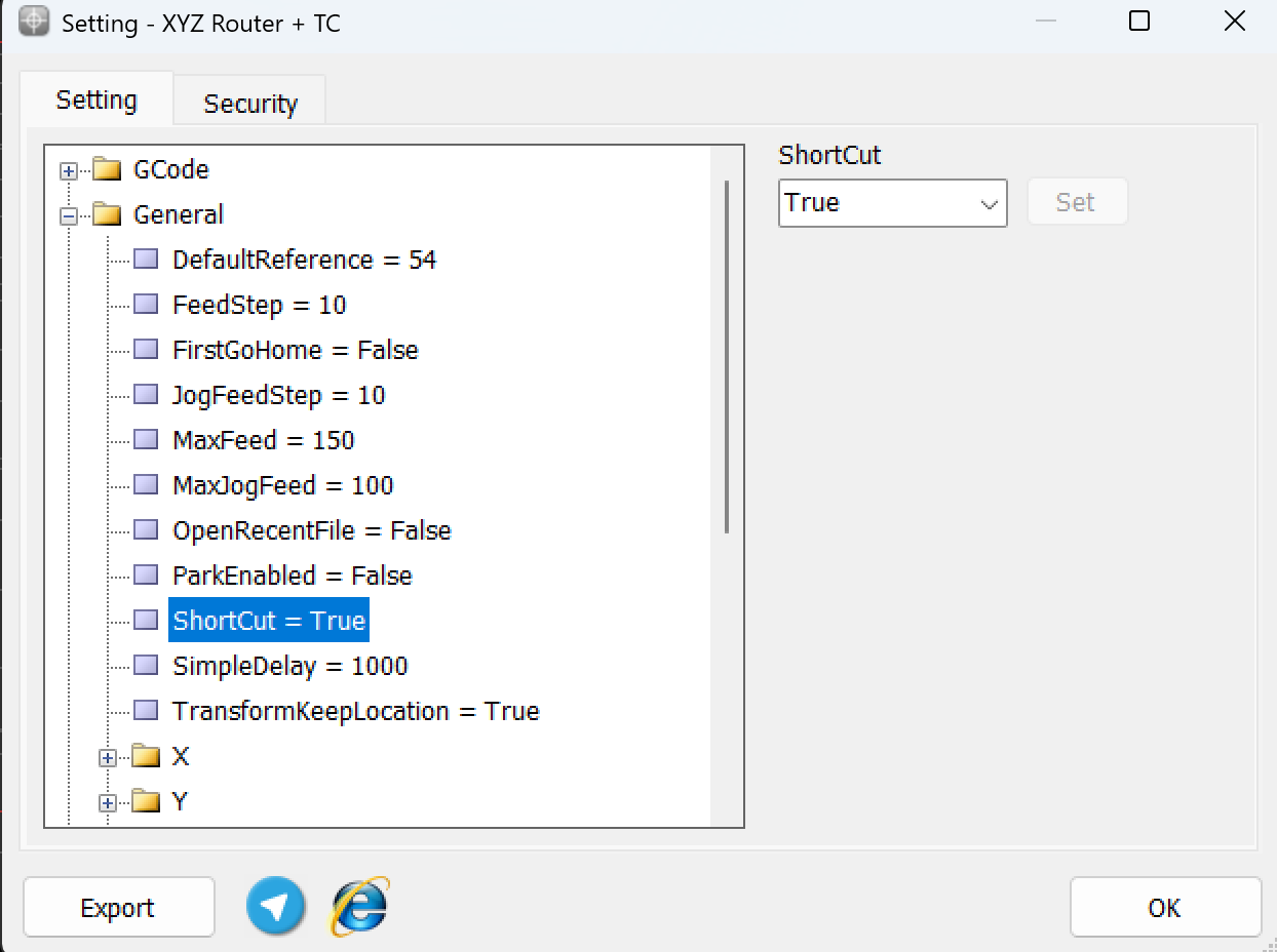
The variable Shortcut is defined as True or False. The ShortCut variable is used for program shortcuts. If this variables False, the machine is moved to the reference point or zero point before the program starts and all codes are executed from the beginning. If this variable is True, the machine is moved to the first cutting and executable line, and the program starts. In this case, codes such as P, T, S, and M that must be used to execute the program may exist before the program starts and are checked, and the last state that the machine must have for executingthe program is taken into account. For example, if the T code is placed first in the Priority section, the tool is first replaced, and if it is the S code, the spindle speed is determined, and so on, the order of execution of the P, T, S, and M codes is determined.• Note that if the Shortcut variable is True in the G-Code section, the Priority variable is used
when I upload a design especially in arches and bows, the designs overlap and it has problem
you may face kind of problem when you upload a design this picture is a sample of the problem
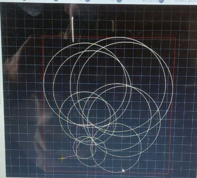
Location : Setting / G-Code / Extention / CNC / Absolute IKJ
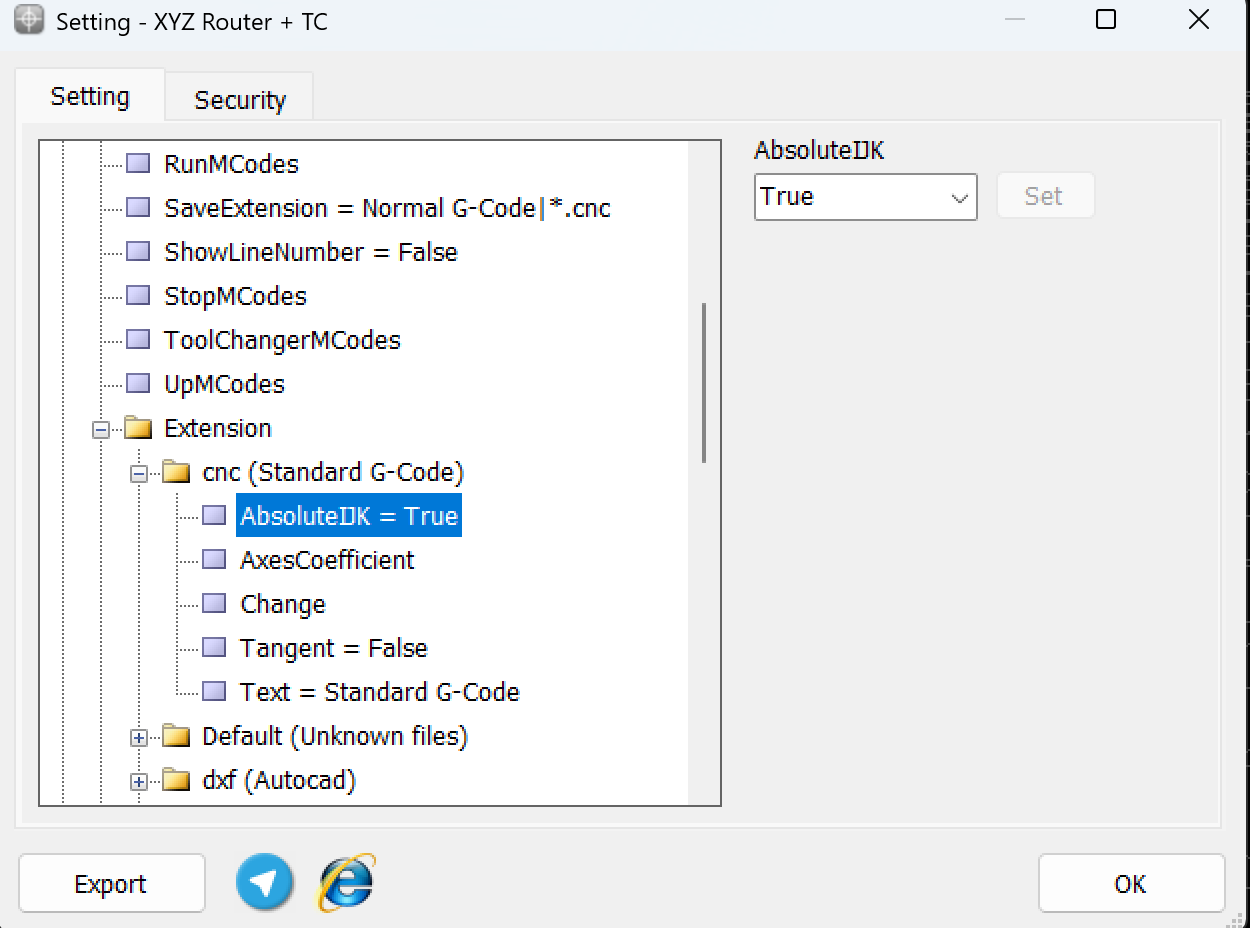
The variable “Absolute IJk” is defined as True or False. If this variable is False and there is a arc in the GCode, the center of the arc is considered as incremental, which means that the center of the arc is adjusted relative to the last position of the machine. If this variable is True and there is an arc in the GCode, the center of the arc is considered as absolute, which means that the coordinates of the center of the arc are adjusted relative to the zero point of the workpiece or the set reference.
The "Absolute IJK" option in the G-Code interface settings pertains to how the coordinates of the center of circles or arcs are defined in machining commands that use G02 and G03 codes for circular or arc movements. In G-Code, I, J, and K are coordinates that define the center of an arc or circle relative to the starting point of the arc.
Absolute IJK: When this option is enabled, the I, J, and K coordinates are considered absolute. This means these coordinates define the center of the arc directly relative to the machine's overall origin (not the arc's starting point). This allows users to specify arc centers more precisely and consistently, especially in complex programs involving multiple circular movements.
Incremental IJK: When the Absolute IJK option is disabled, I, J, and K are defined as relative (incremental) coordinates, meaning the center of each arc is specified relative to its starting point. This mode is suitable for situations where the arc centers need to be determined quickly and easily based on the tool's current position.
If I want to have a more precise homing process what should I do ?
Encoder Zero" or "Zero Encoder" inputs are highly beneficial. This pin, isolated using a Photo Coupler, is available in certain models such as PC-Smart. Its primary function is to accurately detect the Home position or the initial position in a servo motor. This feature is invaluable for machines requiring high precision when returning to the start point, such as complex CNC devices.
The system, by receiving pulses from the encoder, identifies the exact position of the motor the moment the zero pin is activated and informs the controller. This allows the controller to precisely execute operations such as repositioning, axis resetting, and other detailed settings.
How can I set a sensor or micro switch on the table to detect the surface of workpiece automatically
Automatic Zero Setting for Z-Axis Using Surface Detection Sensor
Overview:
To streamline the setup process and enhance precision in machining operations, it is essential for manufacturers to implement an automatic method for setting the zero reference point on the Z-axis. This is achieved through the use of a surface detection sensor, which automatically determines the workpiece level upon contact.
Purpose and Function:
- Surface Detection Sensor: A device typically mounted on or near the tool that detects the surface of the workpiece. It is used to automatically set the Z-axis zero point by precisely detecting the point of contact with the workpiece.
Installation and Setup:
- Sensor Installation:
- Mount the SurfaceDetector sensor securely on the Z-axis assembly or on the tool holder, ensuring it can accurately detect the surface of the workpiece without hindering the tool's operation.
- Connecting the Sensor:
- Connect the sensor to the CNC control system as per the wiring diagrams provided in the installation manual. Ensure all connections are secure and free from interference.
Configuration in Radonix CAM-Pro:
- Configure Input for Surface Detection:
- In Radonix CAM-Pro, navigate to Settings > System > Inputs.
- Assign a specific input channel to the SurfaceDetector sensor. This channel will handle the signal sent when the sensor contacts the workpiece.
- Set Automatic Z-Zero:
- Program the software to recognize the signal from the SurfaceDetector as the trigger to set the Z-axis zero point.
- This can typically be done by entering a specific G-code or macro in the system that executes when the input signal is detected.
Operation:
- Initiating Zero Setting:
- Bring the tool into proximity with the workpiece surface without making contact.
- Start the zero-setting process through the control software or a designated button on the machine interface that activates the SurfaceDetector.
- Automatic Detection and Adjustment:
- The sensor detects the precise moment the tool contacts the workpiece surface.
- The Z-axis is automatically adjusted to set this contact point as the zero reference.
Usage Tips:
- Accuracy Check: After setting the zero point, perform a test cut or measurement to verify the accuracy of the sensor setup.
- Regular Calibration: Periodically calibrate the sensor to ensure ongoing accuracy, especially if the machine experiences significant usage or environmental changes.
- Sensor Maintenance: Regularly inspect and clean the sensor to prevent dust, debris, or damage from affecting its performance.
Troubleshooting:
- Sensor Not Triggering Zero Set:
- Check the sensor’s physical condition for any damage or misalignment.
- Verify the sensor’s connection to the control system and ensure it is active within the software settings.
- Inaccurate Zero Point:
- Re-calibrate the sensor according to the manufacturer’s instructions.
- Ensure that the sensor is not obstructed or dirty, as this can affect its accuracy.
Summary:
The integration of a SurfaceDetector sensor for automatic Z-axis zero setting enhances both the precision and efficiency of CNC operations. Proper setup, regular maintenance, and careful operation are crucial to leverage the full benefits of this technology. Always follow the manufacturer’s guidelines for installation and use to ensure optimal performance and reliability.
The spindle does not shut down automatically after completing the job. We have to turn it off manually .
Sometimes the spindle may continue to run after the completion of a CNC machining job, which can pose safety risks and lead to unnecessary wear on the equipment.
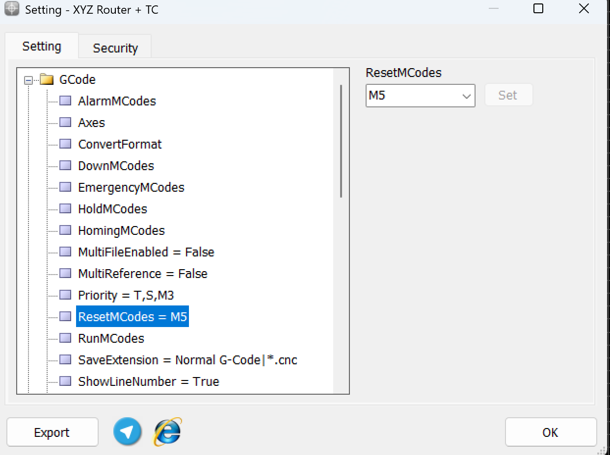
Solution:
To ensure that the spindle automatically shuts down after a job is completed, you can set a specific machine reset G-code within the Radonix CAM-Pro software settings.
Step-by-Step Guide:
Accessing the G-Code Settings:
- Open the Radonix CAM-Pro Software:
- Start the Radonix CAM-Pro software and ensure you are logged in with the necessary administrative or user privileges to make configuration changes.
- Navigate to Settings:
- Go to the main menu and select Settings to access the system settings.
- Navigate to the G-Code tab where G-code specific settings are managed.
Configuring the Reset M-Code:
-
Modify the ResetMCode Setting:
- Within the G-Code settings, locate the entry labeled ResetMCode. This setting determines which M-code is executed at the end of every job to reset the machine state.
- Change the value of ResetMCode to
M5. The M5 G-code command is standard for stopping the spindle in CNC operations.
Example Configuration:
makefile
Copy
ResetMCode = M5
Details:
- M5: This command stops the spindle and ensures that it does not continue to run after the completion of the machining operations.
-
Save Changes:
- After entering the M5 command in the ResetMCode setting, ensure to save the changes by clicking an 'Apply' or 'OK' button, depending on the software interface.
-
Test the Configuration:
- Run a test job to verify that the spindle automatically shuts off after the job completes. This test will confirm that the M5 command is being properly executed as part of the job completion process.
Usage Tips:
- Verification: Always verify that the command has taken effect by observing the spindle's behavior after the completion of a CNC job.
- Safety Practices: Regularly review and test all safety-related settings in your CNC software to ensure they are functioning correctly.
- Documentation: Keep documentation of all settings changes, especially those related to machine safety and operation, to assist in troubleshooting and future reference.
Troubleshooting:
- Spindle Still Running: If the spindle continues to run after implementing the
M5command in the ResetMCode setting:- Check Command Execution: Ensure that there are no overriding commands in your job G-code that might prevent the M5 from executing.
- Software Updates: Check for updates to the Radonix CAM-Pro software that might affect command execution.
- Technical Support: Contact Radonix technical support for further assistance if the problem persists.
Summary:
Configuring the ResetMCode to M5 in Radonix CAM-Pro ensures that the spindle shuts down automatically at the end of a machining job, enhancing safety and preserving machinery. Regular checks and updates are advised to maintain optimal performance and safety standards
If the Set Tool sensor is damaged and needs to be replaced, is there any need to check the case after installing the new sensor?
After replacing the SetTool sensor, the following should be checked:• The NC and NO states of the new sensor should be compared with the previous sensor. If they are not of the same type, the relevant input settings need to be changed.• It is better to re-determine the ToolReference value with the new sensor so that the values recorded and displayed for the tool height in the software are equal to the actual tool height value. The method for performing this process is mentioned in the Radonix manual.• If the previous step is performed, all tools must be SetTooled so that their height can be re-measured.
In the Tool change device, is there a solution to detect a broken tool during operation by the device itself?
In the device with the tool change capability, the ToolToleranceEnabled and ToolTolerance parameters are available. By setting these items appropriately, in a situation where the tool is damaged or broken, this can be automatically detected and the device stopped. Now we have:ToolToleranceEnabled = TrueToolTolerance = desired valueBy setting the first item, the Tool Height Tolerance feature is activated, and the second item specifies the range of this Tolerance. By activating this option, during each tool change, before placing the tool in its parking lot, the tool height is measured once by the tool height sensor. If after measurement, the difference between the current value and the previous value of the tool height is greater than the ToolTolerance value, the broken tool is detected and the device stops.
How to reset the G-code to run again after one round of G-code is executed?
To apply this change, first check in the G-code branch that an M-Code called M30 with a Reset link is defined. Now, if we want to reset the G-code at the end of the job execution, this M-Code must be present at the end of it. If this M-Code is not present, it can be added manually.Note: Note that most posts automatically apply this parameter at the end of the G-code when G-code is generated.
How can I change the speed and acceleration of moving between parts or moving to the parking lot for tool change?
In the following path:Setting System ToolpathThere are parameters called Traverse Velocity and Traverse Acceleration, which are the speed and acceleration of movement, respectively. By adjusting these parameters, it is possible to achieve the appropriate speed and acceleration in movements during G-Code execution.Note: This speed and acceleration are applied to the G0 lines of the G-Code.
We want the Z axis to go up first in the movements and then the Z axis to go down after the other axes have reached the desired point. What is the solution?
In the Radonix axes settings, there is a parameter called Roundtrip that can be changed to True and False. If this parameter is set to True, then that axis will first go to its maximum course and after the other axes (whose Roundtrip is False) have reached the desired point, then this axis will move and go to the position.
If an axis, for example, the X axis, is large and has two motors. In this case, if we want both motors of this axis to play a role in the Homing mechanism synchronously, what changes should be made?
If an axis of a CNC machine, for example, the X axis, is large and has two axes, in this case, if we want them to operate synchronously with each other, one axis should be set in the settings for each motor. One axis is considered X and the other axis is -X, and in the parameters of the -X axis, the Same as item should be set as follows:Same As = -XNow we go to the Home sensors. A separate sensor should be considered for each X axis. While applying Homing parameters to other axes, define the inputs of these two X and -X axes and the relevant links are equal to:Motor 1 : HomePin, X Motor 2: HomePin, -X