Jewelry XYZC
Step-by-Step
Gold CNC Machines Empowered by Radonix: Precision for Modern Jewelry Manufacturing Gold CNC machines are transforming the jewelry manufacturing industry by delivering high precision, enhanced efficiency, and unparalleled versatility in crafting intricate gold designs. Leveraging Computer Numerical Control (CNC) technology, these machines can now produce complex patterns that were once difficult or impossible to achieve using traditional techniques.
At the forefront of this revolution is Radonix, with extensive experience in CNC motion control systems tailored for the jewelry sector.
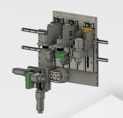
Advanced Multi-Axis Control with Radonix Radonix controllers are engineered to manage complex mechanical structures and support simultaneous control of primary axes including X, Y, Z, and C. As illustrated in Figure 1‑001, our system seamlessly handles demanding configurations often required in multi-head gold CNC machines.
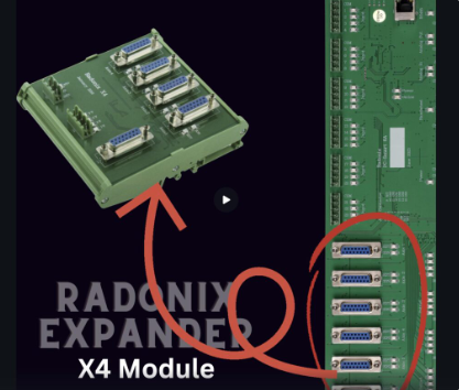
To meet evolving production requirements, Radonix offers a powerful axis expansion feature, known as X4. This feature allows each primary axis to be multiplied by four, enabling control of up to 12 interpolated axes from a single controller — a capability that is critical for high-output jewelry machines.
Sample Configuration Breakdown For better understanding, let’s consider a sample machine setup that Radonix can fully support:
Z-Axis Group: Z1, Z2, Z3
X-Axis Group: X1, X2
Y-Axis: One rotary Y axis
**C-Axis Group: **C1, C2 ,C3
This totals 8 individual axes, which can be expanded through X4 boards to meet even more complex mechanical layouts. Whether the machine operates synchronized tool heads or rotary indexing spindles, Radonix controllers ensure smooth, deterministic motion and reliable process control.
Why Choose Radonix for Jewelry CNC Machines Scalable up to 12 Axes per system
Real-time DXF/G-code processing with visual simulation
Integration with auto tool changers, spindles, engraving modules
Compatible with stepper and servo systems
Remote configuration and support via AnyDesk
Dynamic Axis Configuration — No Macro Programming Required A hallmark of Radonix controllers is their exceptional flexibility in axis configuration. Unlike traditional systems that require complex macro programming, Radonix enables users to define and modify all machine axes directly through the settings interface. This intuitive approach simplifies the entire setup process, allowing operators to adapt their machines quickly and efficiently.
By simply selecting the desired axis configuration from the settings menu, users can determine how many Z, C, or Y axes are active in the system—depending entirely on the mechanical design and production requirements. This eliminates the need for programming expertise and reduces commissioning time dramatically.
Simplified Setup and Maximum Adaptability This software-defined flexibility represents a major advancement in CNC control technology. It allows manufacturers to easily reconfigure machines for different production scenarios—whether they are switching between single-head and multi-head operations or between rotary and linear motion systems.
Modern Radonix controllers further enhance this adaptability by supporting:
Automatic recognition of connected hardware modules
Dynamic axis mapping and configuration changes
Instant activation/deactivation of additional axes through X4 expansion
As a result, operators can fine-tune and optimize their machine setup in real time, without stopping production or rewriting control macros.
Perfect for Variable and Custom Production This level of flexibility is particularly valuable for custom jewelry manufacturing and other industries where each project may demand a unique mechanical configuration. Whether increasing the number of Z axes for multi-head engraving or adding an extra C or Y rotary axis for precision cutting, Radonix ensures that every setup can be adapted swiftly and with minimal effort.
The Radonix X4 Expander is a specialized board designed to replicate the pulse and direction signals of a single axis into up to four identical outputs. By distributing these signals simultaneously to multiple motor drivers, it allows you to operate multiple motors on the same axis in perfect synchronization. This is particularly beneficial in applications such as jewelry and gold CNC machining, where multiple spindles or heads (e.g., multiple Z axes or dual X axes) need to move in unison.
Key Benefits Expand 1 Axis to 4 Replicates step and direction signals from one axis into four separate outputs. Ideal for multi-head or multi-motor setups on the same axis. Line Drive Input & Output Uses industry-standard line driver signals to ensure high noise immunity. Delivers reliable performance in demanding CNC environments. NPN Isolated Input Protects against electrical noise and voltage spikes. Improves overall system safety and longevity. Easy Integration Standard DB25 connectors simplify wiring and reduce setup time. Straightforward plug-and-play expansion—no extra motion-profile programming needed. Versatile Applications Perfect for jewelry and gold CNCs requiring multiple synchronized cutting or engraving heads. Enhances throughput by enabling multiple motors to work simultaneously on the same axis.
**How It Works **Input Signals
The main controller outputs standard step/direction signals for a single axis.
Signal Duplication
The X4 Expander receives these signals and replicates them across four separate channels.
Motor Drivers
Each channel can be connected to its own motor driver, allowing multiple motors to move in sync.
Seamless Integration
Thanks to NPN-isolated inputs and line driver outputs, interference is minimized, ensuring precise, reliable motion.
In short, the Radonix X4 Expander provides a powerful way to scale your CNC system.
This level of flexibility is particularly valuable for custom jewelry manufacturing and other industries where each project may demand a unique mechanical configuration. Whether increasing the number of Z axes for multi-head engraving or adding an extra C or Y rotary axis for precision cutting, Radonix ensures that every setup can be adapted swiftly and with minimal effort.
Software Infrastructure The user-friendly interface developed by Radonix represents a major step forward in simplifying CNC operation and setup. Designed with both functionality and accessibility in mind, this interface offers a practical and intuitive user experience that allows operators—whether beginners or professionals—to configure and start their machines with minimal effort.
Through clear parameters, logical menus, and streamlined workflows, the Radonix UI reduces the learning curve and enables quick adaptation to any production environment. Users can easily define machine settings, adjust motion parameters, and initiate machining processes without the need for extensive training. This not only minimizes setup time but also enhances overall productivity on the shop floor.
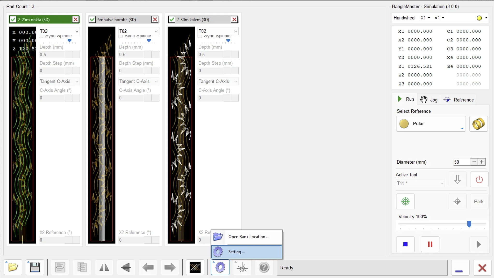
Radonix Jewelry System — BangleMaster Simulation Interface & Digital Input Guide
- **Introduction **The BangleMaster Simulation Interface developed by Radonix allows jewelry manufacturers and designers to simulate toolpaths and machine operations before executing them on an actual CNC or lathe. While the software focuses primarily on bangle production, the same principles apply to a wide range of jewelry manufacturing processes — including rings, pendants, and ornamental components.
The system provides visual toolpath simulation, real-time motion tracking, and axis feedback to ensure precision, prevent collisions, and optimize machining sequences before physical cutting begins.
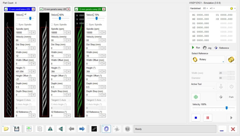
- Main Workspace Overview When the software is launched, the main workspace appears, divided into three key sections:
Menu & Toolbar (Bottom-Left Corner)
Simulation Viewer (Main Canvas)
Machine Controls & Status Panel (Right Side)
**2.1 Simulation Viewer ** Central Gray Area: The primary workspace where toolpaths and motion simulations are displayed.
Empty by default when no job is loaded.
Toolpath Visualization: Once a file or design is loaded, the generated toolpath is shown here, including tool geometry, trajectory lines, and cutting animations.
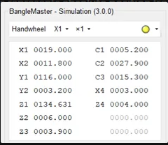
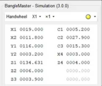
2.2 Machine Coordinates Panel (Top-Right) Displays the live and target coordinates of the machine’s active axes. Axes may include:
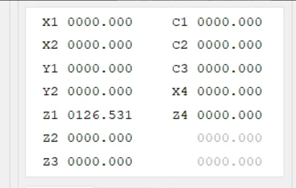
X1, X2, X4 (Linear axes)
Y1, Y2 (Linear or rotary, depending on configuration)
Z1, Z2, Z3 (Vertical axes or tool groups)
C1, C2, C3, C4 (Rotary axes)
Each coordinate shows:
Current Value: The present position of the tool relative to the reference point.
Target Value: The next programmed position, which updates dynamically during jogging or simulation.
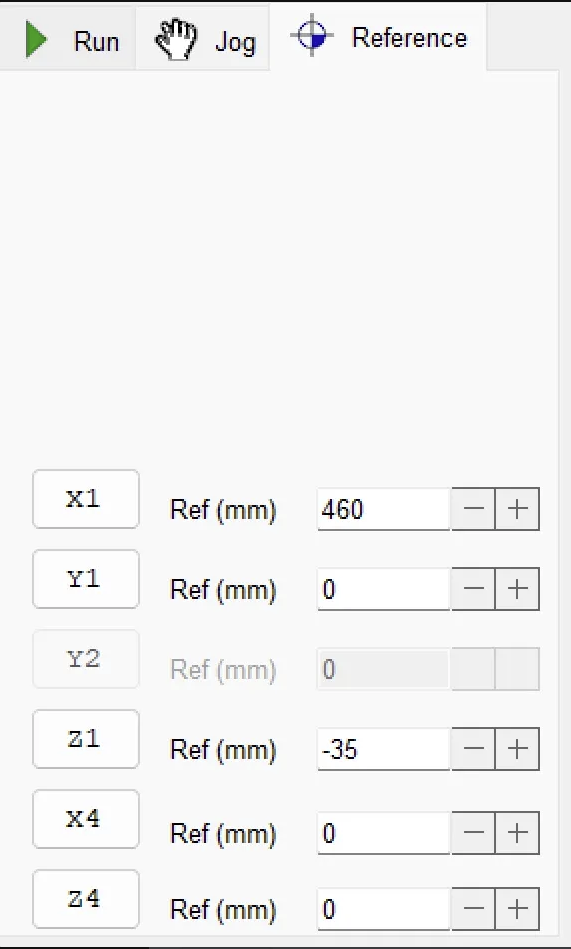
2.3 Run / Jog / Reference Controls
Run: Starts the simulation or executes the toolpath.
Jog: Enables manual movement of axes for positioning the tool at a specific location.
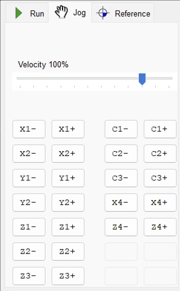
Reference: Returns all axes to their workpiece start point to ensure coordinate synchronization.
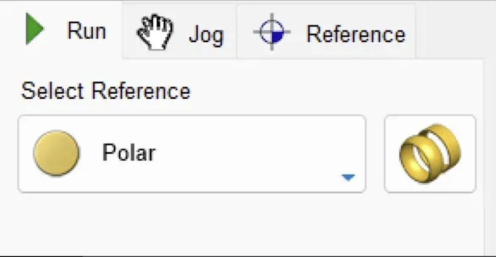
2.4 Reference Modes & Diameter Settings Select Reference (Polar / Cartesian): Choose between coordinate systems depending on design type. Polar is ideal for bangle and ring operations; Cartesian for flat or linear tasks.
Diameter (mm): Sets the actual diameter of the bangle or cylindrical workpiece. Adjusting this ensures that the simulation matches real-world proportions.
2.5 Active Tool & Power Controls Active Tool (T11, T12, etc.): Displays the selected tool in the turret. Click to choose another tool from the library (e.g., T1 roughing, T2 finishing).
Tool Down / Power Buttons:
Lower or raise the tool.
Power On/Off toggles the virtual machine’s status or actual hardware connection.
2.6 Velocity Slider The Velocity 100% slider controls feed speed in simulation or real cutting mode. Move left to reduce feedrate for safer tests, or right to accelerate once paths are verified.
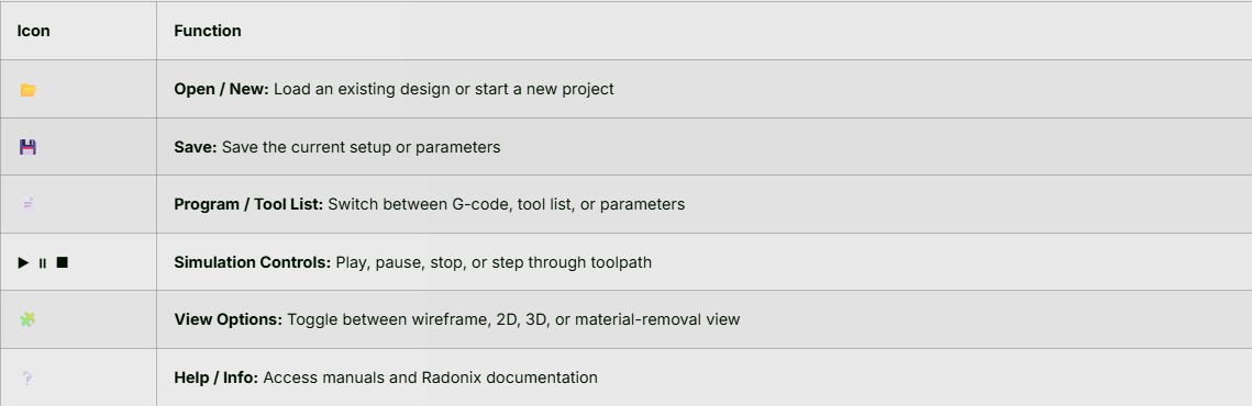
3.Bottom Toolbar
4. Basic Workflow
- Load or Create a Job
- Click the folder icon to open an existing design or start a new bangle layout.
- Set Reference
- Choose between Polar or Cartesian references depending on your design approach.
- Enter Workpiece Dimensions
- Adjust Diameter (mm) for your bangle or cylindrical item.
- Select a Tool
- In the Active Tool dropdown, pick the correct tooling (e.g., T11).
- Check Toolpaths
- Ensure the coordinates (X, Y, Z, and C) make sense and do not exceed the machine’s limits.
- Simulate
- Hit Run to visualize tool motion.
- Use Pause/Stop to inspect any point in the process.
- Adjust & Repeat
- If the path needs altering, make changes in your CAM settings or tool parameters and re-run the simulation.
- Adjust feedrate (Velocity slider) to see how speed changes might affect the cut.
5. Jogging & Referencing
- Jog Mode: Click Jog to manually move the virtual machine axes. This is especially helpful for verifying safe distances or checking clearances around the bangle blank.
- Reference: Clicking this will send all axes to their machine-zero positions. Always reference before your first job to ensure accurate coordinate alignment.
6. Saving & Exporting
- Save Project: Use the save icon or File → Save As to store the project, including tool data and machine settings.
- Export G-Code: If supported, you can export the final toolpath as G-code or a similar machine-readable format to run on your actual CNC lathe.
7. Common Controls & Indicators
- Park: A quick button to move the active tool to a safe “parking” position.
- Tool Orientation: Indicated by a small icon or text near the Active Tool field.
- Status Message (Bottom Right): Displays Ready, Running, Paused, or any error messages.
8. Tips & Best Practices
- Always Reference First: Making sure the software/machine coordinate system is correct avoids collisions.
- Check Dimensions Carefully: Confirm the diameter and thickness of your workpiece to get an accurate simulation.
- Slow Down During First Simulation: Use the velocity slider to run the simulation slowly if you are testing new toolpaths.
- Save Frequently: Save your project after each significant change to avoid losing work.
9. Troubleshooting
- Simulation Not Visible: Make sure you’ve loaded a valid job file and your display options are turned on (wireframe or solid view).
- Incorrect Dimensions: Double-check your Diameter (mm) field and machine references.
- Axis Values Not Changing: Ensure the Jog mode is enabled or your G-code is valid.
- Tool Not Appearing: Confirm that the selected Active Tool is valid and loaded in your tool library.
10. Additional Resources
- Visit the Radonix support site or your in-house documentation for tutorials on creating bangle toolpaths.
- Check out video walkthroughs (if available) that demonstrate step-by-step job setup and machine operation.
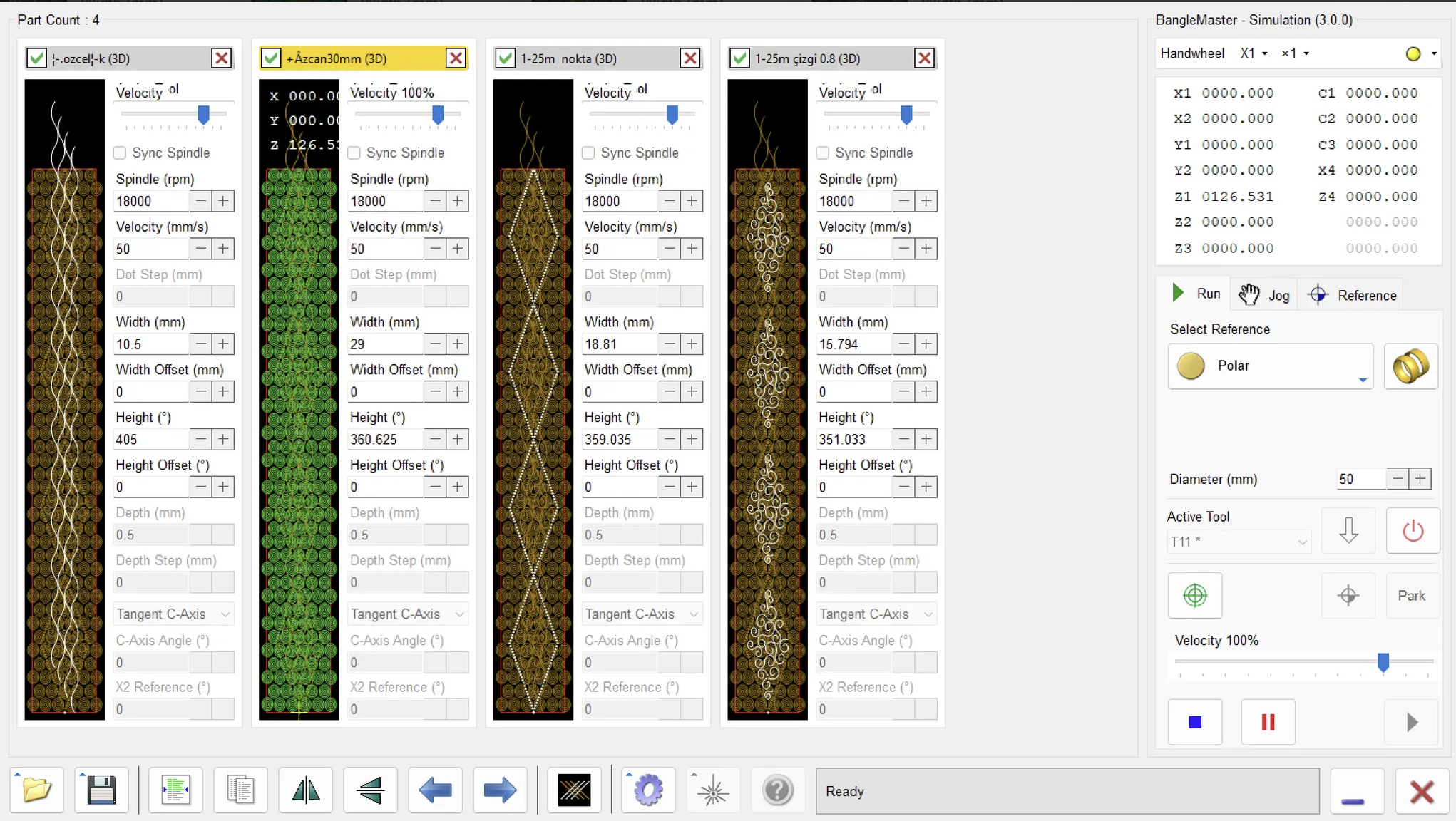
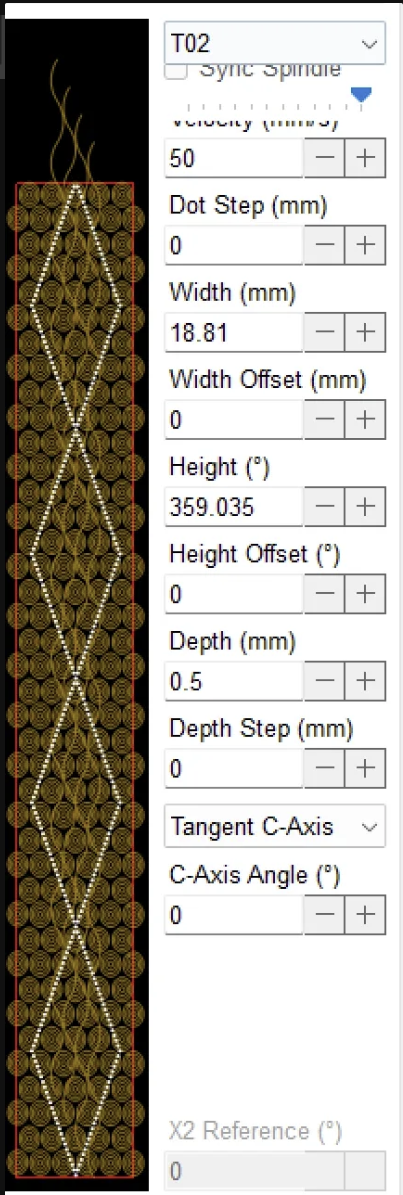
- Preview Window (Left Side)
- Shows a 2D rendering of the design or pattern. In the screenshot, a repeating ornamental pattern is shown in gold with a white diamond-shaped path running vertically.
- The red rectangle around the design indicates the bounding box for the piece.
- Above the preview is the title bar with the filename, “1-25m nokta (2D)”, and two icons:
- Green Check Mark: Confirms or applies the current settings/operation.
- Red X: Closes or cancels the current window.
- Velocity Slider (Top Right)
- A quick, on-screen feed-rate override slider. Moving this slider to the right typically increases the feed rate; moving it to the left slows it down.
- This is handy for live adjustments while testing or cutting (especially if the material or tool demands more caution).
- Sync Spindle (Checkbox)
- When enabled, the spindle speed may adjust in tandem with feed rate changes.
- Useful if you want to maintain a particular chip load or cutting ratio (so if you slow the feed, the spindle slows accordingly).
- Spindle (rpm) = 18000
- Sets the primary spindle rotation speed in revolutions per minute.
- 18,000 rpm is a common speed for detail engraving on softer metals or wax patterns.
- Velocity (mm/s) = 50
- The default linear feed rate at which the tool moves through the material.
- Adjust as needed for different materials or when more precise (slower) cutting is required.
- Dot Step (mm) = 0
- Used in certain drilling or “dot” patterns, indicating the distance between individual plunge points.
- A value of 0 typically means the system is not generating discrete dot steps, or it’s effectively treating this as a continuous path.
- Width (mm) = 18.81
- Represents the physical width of the design or bounding box in millimeters.
- If you need a piece to fit a specific ring blank or jewelry dimension, this is where you confirm or adjust that width.
- Width Offset (mm) = 0
- Shifts the design left or right.
- Setting it to 0 means the design’s width is not offset from its current reference point.
- Height (°) = 359.035
- Indicates the angular height (circumference) in degrees of the design—often used for ring or cylindrical layouts.
- A value close to 360° suggests the design is intended to wrap almost fully around the circumference of a ring or cylinder.
- Height Offset (°) = 0
- An angular shift of the design on the ring’s circumference.
- 0° means no rotational offset; if you needed to rotate the pattern for alignment, you’d enter a different value here.
- Depth (mm) = 0.5
- The cut depth (in millimeters) for the current operation.
- In engraving or milling, this defines how far into the material the tool will cut.
- Depth Step (mm) = 0
- Determines whether the cut is broken into incremental passes (e.g., if you wanted to cut 0.5 mm in two passes of 0.25 mm each, you’d set this to 0.25).
- 0 indicates a single pass at the full 0.5 mm depth.
- Tangent C-Axis (Dropdown)
- Specifies how the C-axis (rotational axis) handles the tool path:
- Tangent usually means the tool remains tangent (perpendicular) to the surface around the ring.
- Other options might include “Fixed” or “Normal,” depending on the machine’s capabilities.
- Specifies how the C-axis (rotational axis) handles the tool path:
- C-Axis Angle (°) = 0
- A manual rotation offset for the C-axis.
- If you want the entire pattern rotated around the cylinder or ring, you can change this angle.
- X2 Reference (°) = 0
- Often used in dual-axis or advanced rotary systems to reference a second rotational angle.
- A value of 0° means there is no secondary angular offset.
1-Comprehensive Guide to Digital Inputs of Radonix Controllers
Digital inputs on Radonix controllers are identified by the prefix I. followed by a sequential number (e.g., I.01, I.02, ...). These inputs are opto-isolated, providing high noise immunity and protection against transient voltages. This guide aims to explain the specifications, wiring, and software configuration of all input channels to support error-free installation, troubleshooting, and operation.
- Electrical Specifications
| Feature | PC-Pro | PC-Smart |
|---|---|---|
| Rated Voltage | 24 VDC (18–28 V) | 24 VDC (12–24 V) |
| Isolation Type | Optocoupler | Optocoupler |
| Opto LED Current | ≈ 5 mA with 4.7 kΩ resistor | Same |
| Input Channels (example) | 16 DI on 2A model, 24 DI on 4A, 32 DI on 6A | 8 DI on 3AS, 16 DI on 4A |
| Selectable Mode | NPN (Sink) or PNP (Source) via on-board jumper | Same |
Logic Definition:
- NPN (Sink): Activated when input is connected to 0 V
- PNP (Source): Activated when +24 V is applied to the input
- Switching Between NPN and PNP Modes
- Turn off the controller.
- Locate the jumper/selector next to the DI connector and set it to either NPN or PNP.
- Power on the controller and verify input status in CAM-Pro software (InPort LED On/Off).
- Standard Wiring Diagrams
4.1. NPN (Sink) Mode – See Figure 10 (Top)
| Connection | Wire Color | Description |
|---|---|---|
| Sensor +24 V | Brown → +24 V panel | Sensor power supply |
| Sensor Output | Black → I.n | Pulls input low when activated |
| Common | Blue → COM (0 V) | Common ground reference for controller |
4.2. PNP (Source) Mode – See Figure 10 (Bottom)
| Connection | Wire Color | Description |
|---|---|---|
| Sensor +24 V | Brown → +24 V | Sensor power supply |
| Sensor Output | Black → I.n | Applies +24 V when activated |
| Common | Blue → COM (+24 V) | Common reference (positive in this mode) |
Mechanical Switches: Connect the common terminal to COM and output terminal to I.n.
- Pin & Connector Naming
| Terminal Row | Description |
|---|---|
| I.01 … I.08 / I.01 … I.32 | Input channels numbered sequentially |
| COM | Common reference (0 V for NPN / +24 V for PNP) |
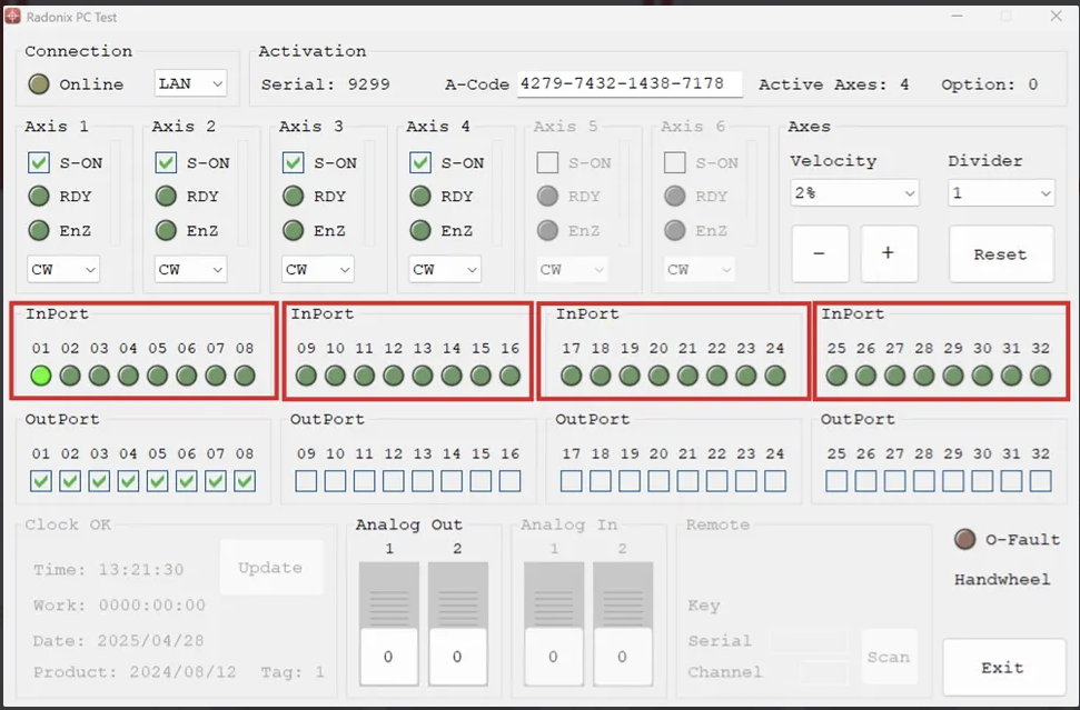
CAM-Pro Test Software
- In the opened window of CAM-Pro Test software, under the InPorts section, you can verify the correctness of your wiring by observing the input status after making connections as described above.
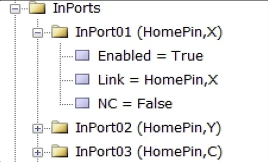
Configuration and Settings in CAM-Pro Software
- To link a digital input to a specific function (e.g., activating a sensor), go to:Settings → System → InPorts, then assign the desired output name (e.g., Homepin, X) to the input channel (e.g., I.nn).
- Save the changes and test the setup (the indicator or device should respond according to the software command).
Summary of Inputs in Radonix Jewelry Interface:
- ChangeParameter, Clamp: Allow manual control for adjusting machine settings or operating the clamp.
- Emergency: Triggers an immediate machine stop for safety.
- Handwheel Settings (Handwheel_1, Handwheel_10, HandwheelA, HandwheelX): Provide manual control over machine movements at different increments or axes.
- HolderJack: Sensors monitor the jack’s position, ensuring it's correctly placed before operation starts.
- Home, HomePin: Initiate and configure the homing process for machine calibration.
- Jog, Reference, SetReference: Control manual jogging of the machine, referencing positions, and setting new reference points for operations.
- ScannerOffSensorPin, ScannerOnSensorPin: Enable or disable scanner functions for accurate workpiece measurement.
- SetToolHeightManual: Manually set tool height in machines lacking automatic sensors.
- Stop, Stop-Reset-ZUp, Stop-ZUp: Manage machine stops with options to reset or maintain the Z-axis position.
- ToggleOutPort: Toggle output ports, useful for controlling external devices or functions.
- ToolHeightSensorPin, ToolHolderSensorPin: Detect the correct height of tools and ensure the tool holder is in the proper position for operation
Comprehensive Guide to Digital Outputs in Radonix Controllers
-
PC-Pro:
Terminal rows labeled
O.01 – O.nn. There is no dedicated COM terminal; outputs share the board’s common ground. -
PC-Smart:
Terminals labeled
O1…O4plus one separate COM terminal at the bottom of the connector, serving as the shared ground for all relays.
Accessing the Main Settings
1. Quick Introduction
Digital outputs are labeled with the prefix O. (e.g., O.01) and have different structures depending on the controller family:
| Controller Family | Output Type | Max Current | Internal Protection | Typical Applications |
|---|---|---|---|---|
| PC-Pro | Open-Collector NPN (Low-Active / Sink) | ≤ 300 mA per channel | TLE6225 IC + flyback diode + 10 kΩ resistor (see diagram below) | Signal lamps, relay coils, contactor coils |
| PC-Smart | 1A Relay (Double Terminal) + 24 V Zener Diode | ≤ 1 A (relay contact) | Internal relay and Zener diode to suppress back EMF | Pneumatic valves, solenoids, small DC motors |
Important Warning (PC-Pro):
2. Pinout & Connector Description
-
PC-Pro:
Terminal rows labeled
O.01 – O.nn. There is no dedicated COM terminal; outputs share the board’s common ground. -
PC-Smart:
Terminals labeled
O1…O4plus one separate COM terminal at the bottom of the connector, serving as the shared ground for all relays.Summary of Outputs in Radonix Jewelry Interface :- AxisPin: Controls which axis is activated by the X4 board, allowing selective movement of machine components like X1 or Z1 axes.
- BrakePin: Engages and release the brake to the machine in a safe state when it goes online.
- ClampPin: Operates the gripper on the spindle, enabling it to open and close as needed for holding or releasing items.
- CleanerPin: Activates a system to blow air, typically used to clean the work area or clear debris.
- CoverPin: it can enable and disable the cover of the tool changer .
- HolderJackPin: Operates a jack that adjusts the holder or tooling position (specific function needs clarification).
- LaserEnabledPin, LaserPointerPin, LaserPowerPin: Manage laser settings for operations like engraving, pointing for alignment, and power control for laser intensity.
- ReadyPin: Indicates when the machine is ready to operate, ensuring all systems are go for motion.
- ScannerPin: Activates the scanner when changing workpiece diameters, assisting in accurate dimensioning.
- SpindleJackPin:
- ToolCCWPin, ToolCWP, ToolCCWP: Manage and enable the VFD to enable forward .
- ToolHeightPin: Activates a mechanism to adjust or measure tool height, crucial for precision work.
- ToolPin: Identifies and selects the correct tool for operation, particularly when multiple options are available. ToolPin,4 / ToolPin,5
- ToolPowerPin: can enable and manage contactor which actives and enable the spindle
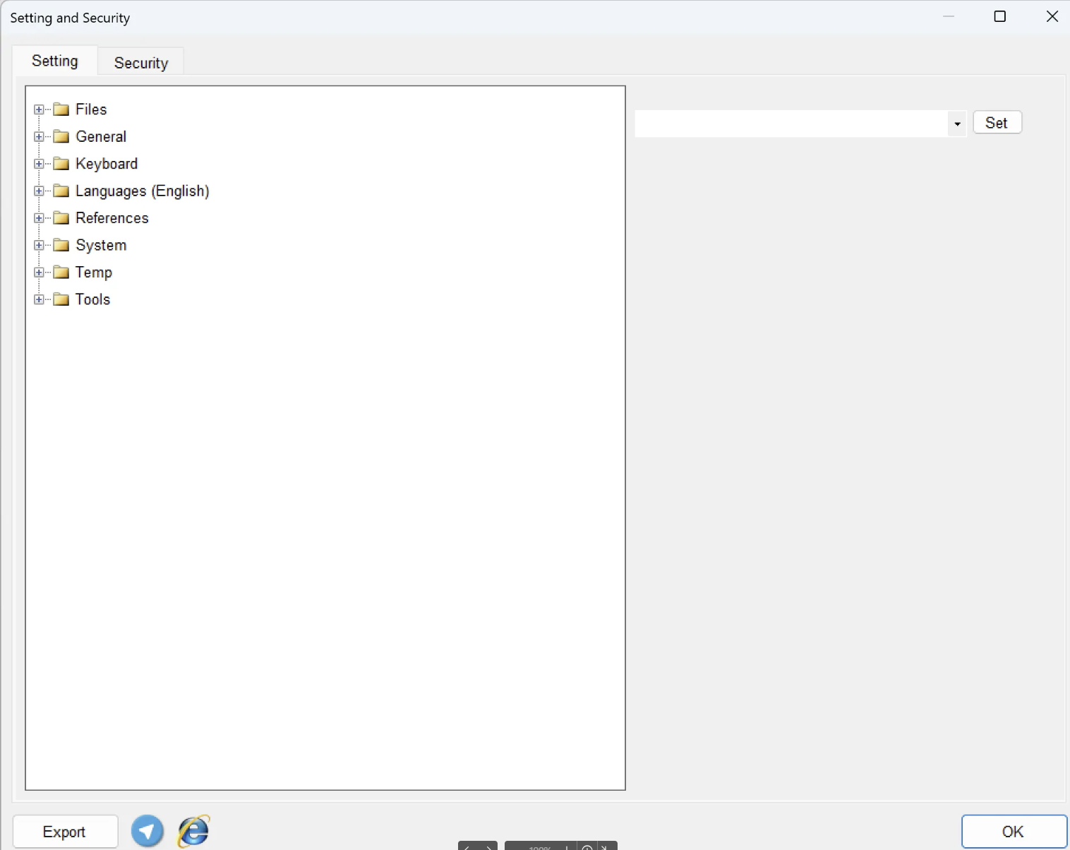
- Open the Settings Panel
- Click on the Setting button in the Radonix Jewelry Interface toolbar.
- The Setting and Security window will appear, displaying two tabs: Setting and Security.
- Setting Tab
- Under the Setting tab, you will find eight distinct configuration branches:
- Files
- Purpose: Manage file handling, such as loading, saving, importing, or exporting project files.
- Use Case: If you need to open a previously saved design or export the current project to share with colleagues, adjust the file paths and storage locations here.
- General
- Purpose: Contains general system parameters (e.g., default speeds, safe heights, and other global machine settings).
- Use Case: Fine-tune overall performance, default spindle speeds, safe Z-levels, and other core parameters that affect how the machine operates.
- Keyboard
- Purpose: Customize or review keyboard shortcuts and hotkeys.
- Use Case: Improve workflow by assigning frequently used functions to specific key commands, or review existing shortcuts for faster navigation.
- Languages (English)
- Purpose: Select and configure the software interface language.
- Use Case: If your team or client requires a different language, check here to see if multiple language packs are installed.
- References
- Purpose: Configure reference points, coordinate systems, or any auxiliary data the software uses during design or cutting.
- Use Case: Adjust origin offsets, manage measurement references, or set up location guides for consistent part alignment.
- System
- Purpose: Access system-level configurations for the machine or software environment (e.g., device drivers, hardware communication).
- Use Case: If you’re troubleshooting hardware or adjusting advanced driver settings, this is where to look.
- Temp
- Purpose: Manage temporary files or define the location for cached data.
- Use Case: Clear or relocate temporary folders to ensure optimal performance and avoid cluttering your main drive.
- Tools
- Purpose: Organize and edit the tool database or tool-related settings, such as cutter diameter, length offsets, or tool libraries.
- Use Case: When introducing a new tool (e.g., a specific drill bit or mill cutter), add or adjust it here so the software can properly calculate feeds, speeds, and paths.
- Files
- Under the Setting tab, you will find eight distinct configuration branches:
- Security Tab
- This adjacent tab often contains settings related to software licensing, user access levels, or password protection. (Availability and contents vary depending on your Radonix system configuration.)
- Tip: Consult your administrator before making changes to security settings to avoid unauthorized modifications.
General :
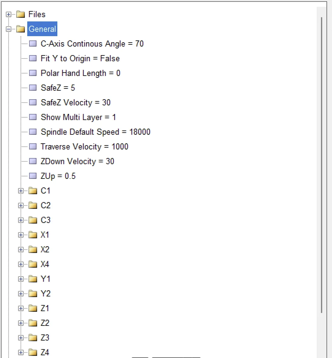
| # | Parameter & Value | Technical Meaning | Practical Tip (Operational) | |
|---|---|---|---|---|
| 1 | C Axis Continuous Angle | Maximum angle the C-axis can rotate in one direction without stopping. | 15° means rotation continues if segment gap > 15°. Use smaller values for fine details (e.g., logos), larger for long arcs. | |
| 2 | Fit Y to Origin | Defines whether software should auto-zero the Y-axis. | False: Y stays as in CAD/G-code. True: Lowest Y of the design aligns with machine zero. | |
| 3 | Polar Hand Length | Virtual radius length used in polar engraving mode. | 0 disables polar mode. Set a radius value to enable accurate circular paths. | |
| 4 | SafeZ | Safe height of Z-axis before rapid moves. | Should be higher than the tallest clamp or workpiece. Bigger = safer but slower. | |
| 5 | SafeZ Velocity | Speed of Z-axis moving to/from SafeZ. | Higher speed saves time, but may cause vibration on light machines. Tune based on spindle mass. | |
| 6 | Show Multilayer | Enables display and control of multiple layers/passes. | 1 (ON): Separate control per depth/color layer. 0: Simplified interface for single-pass jobs. | |
| 7 | Spindle Default Speed | Default spindle RPM when no S command is present in the G-code. | 18,000 rpm is common for fine gold/silver tools. Lower for soft materials to avoid melting or tool slippage. | |
| 8 | Traverse Velocity | Rapid movement speed of X and Y axes (non-cutting). | Higher speed reduces idle time. But ensure machine stiffness prevents vibration. | |
| 9 | ZDown Velocity | Speed at which Z plunges into material. | If chattering or tool breakage occurs during plunge, reduce this value. | |
| 10 | ZUp | Lift distance (or sometimes speed) between passes. | 0.5 mm is often enough to release chips without wasting time. Adjust as needed. |
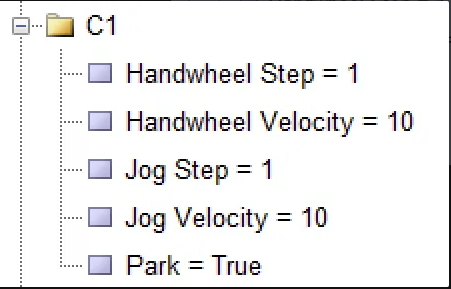
| # | Parameter & Value | Technical Meaning | Practical Tip (Operational) |
|---|---|---|---|
| 1 | Handwheel Step = 1 | Each notch of the handwheel moves the axis by 1 mm (or 1° for rotary axes). | Ideal for precise tool setting or plate contact. For finer motion, reduce to 0.01 or 0.1. |
| 2 | Handwheel Velocity = 10 mm/s | Maximum movement speed when rotating the handwheel. | Higher speed = faster positioning but lower control accuracy. Use 5–8 mm/s for delicate work, up to 20 mm/s for large parts. |
| 3 | Jog Step = 1 | Each press of the JOG button moves the axis exactly 1 mm. | Useful for fine positioning in Z or centering tools. Use 5 or 10 mm for longer travel. |
| 4 | Jog Velocity = 10 mm/s | Movement speed during continuous jog (Hold to Move). | If motion feels too slow, increase to 20 mm/s. Always release button before a possible collision. |
| 5 | Park = True | At the end of a program or on M30 command, axes return to predefined park positions. | Recommended for safe tool or part replacement (e.g., X=0, Z=SafeZ, C=0°). Set to False if you want the machine to stop in place. |
Tool System & Parking Configuration
Radonix Jewelry CNC – Tool Setup Guide
1. Initial Preparation
- Home the machine to establish machine zero using the home sensors.
- Reduce Jog speed to a low level (e.g., 10%) for precise manual control.
- Mount the reference tool T11 in the spindle — all parking positions will be set based on this tool.
2. Parking Setup for Rotary Magazine Tools (T11 to T19)
- Slowly lower the spindle using the Z-axis until the tip of T11 is aligned with the mouth of a magazine slot.
- If the tool slot is not directly aligned, rotate C1 axis in small steps until the tool aligns perfectly with the pocket.
- When the tool slides smoothly into the slot (no resistance or collision), note the X, Z, and C1 coordinates from the axis status window (this represents absolute position from the machine home).
1.Go to Settings → Tools → Z,C, select slot T11, and enter the recorded X, Z, and C values, then click Save.
- Manually command the spindle to unload the tool from the magazine.
- Repeat the same procedure for tools T12 to T19: each time, rotate C1 until the next slot is aligned with the spindle and enter the new coordinates into the corresponding tool slot.
3. Precise Setup of Linear Tools T02 (Z2) and T03 (Z3)
Step 1 — Finding the Workpiece X-Zero Using T11*
Assume that the magazine operation is complete, and T11 is already mounted on the main spindle (Z1).
At this point, the C1 axis is no longer involved.
In the Active Tool window, select T11 (already mounted on the spindle).
Go to the Jog tab.
Use Z1- / Z1+ to adjust the height, and X1± to gently bring the tip of T11 into contact with the outer edge of the ring.
Read the Absolute X1 value — e.g., 234.650 mm.
Subtract the actual tip radius of T11 (e.g., 0.15 mm):
Xref = 234.650 − 0.15 = 234.500 mm
This is your workpiece X-zero coordinate.
Step 2 — Setting Offset for Linear Tool T02 (Mounted on Z2)
In Active Tool, select T02, then press the ↓ arrow. → The controller activates only Z2 (no magazine movement or C1 rotation).
Use Z2- to lower the tool, and X1± to bring the tip of T02 exactly to the same contact point on the ring’s edge.
Read Absolute X2, subtract T02’s tip radius (e.g., 0.20 mm):
X2′ = X2abs − 0.20
Calculate the X offset:
ΔXT02 = X2′ − Xref
Go to Settings → Tools → T02, enter the ΔX in the X offset field, and Save.
If you adjusted Y1 during the touch, calculate the same ΔY and enter it in the Y field as well.
Step 3 — Setting Offset for Linear Tool T03 (Mounted on Z3)
Select T03, then press ↓ to activate Z3.
Use Z3- and X1± to bring the tip of T03 to the same reference contact point.
Read Absolute X3, subtract T03’s tip radius:
X3′ = X3abs − Tip Radius
Calculate:
ΔXT03 = X3′ − Xref
Save ΔX in Settings → Tools → T03.
. Saving and Final Testing
After entering all tool positions, click set or save to write the values into the software.
Create a test sequence that calls each tool in order: T11 to T19, then T02 and T03. The sequence should only include tool change commands and return to Safe Z.
Run the program as a Dry-Run at 10% speed. Observe that for each tool change, Z and C axes move precisely to their stored coordinates, the tool enters the pocket smoothly, and exits without collision.
If you notice any misalignment or resistance, stop immediately, re-align the tool using Jog, update the coordinates, and repeat the test.
Tool change process :
for starting initialization tool change there are some steps to knowing , it’s so important to execute all steps step by step in this order
You will face with some parameters
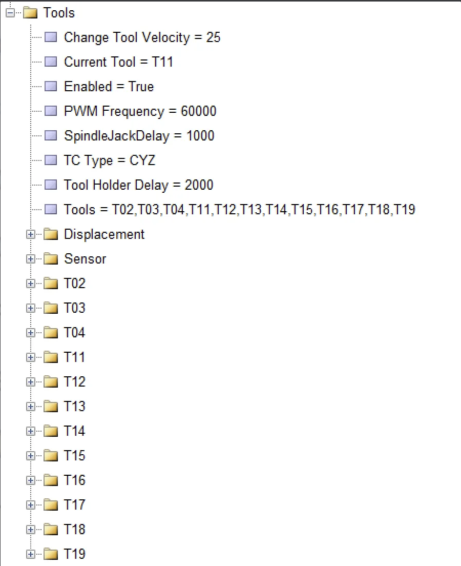
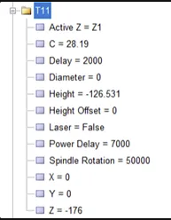
Below is an overview of the Tools configuration section, explaining the main parameters and how they typically work in a jewelry/CNC environment.
ey Parameters
- Change Tool Velocity = 25
- Purpose: The speed at which the machine changes from one tool to another (e.g., how quickly the tool carousel rotates or the spindle parks/un-parks).
- Usage Note: A high ver value can speed up tool changes but might introduce more mechanical stress or risk of misalignment.
W2. Current Tool = T11
- Purpose: Indicates which tool is presently mounted in the spindle or active for cutting/engraving operations.
- Usage Note: This updates automatically when the machine performs a tool change, or you can set it manually if you’re updating the machine state.
- Enabled = True
- Purpose: Toggles the tool management system on or off.
- Usage Note: When set to False, tool-change commands or offsets might be ignored by the system.
- PWM Frequency = 60000
- Purpose: Sets the pulse-width modulation (PWM) frequency used to control the spindle or other components (e.g., laser, motor).
- Usage Note: A higher frequency can lead to smoother motor operation or finer control, but always stay within hardware specifications.
- SpindleJackDelay = 1000
- Purpose: A delay (in milliseconds) that ensures the spindle is raised or “jacked up” before/after a tool change.
- Usage Note: Prevents collisions or incorrect loading by giving the spindle enough time to move to a safe height.
- TC Type = CYZ
- Purpose: Defines the type or model of the tool changer in use (e.g., “CYZ,” “Umbrella,” “Turret”) or you can determine which axis is involved in this process.
- Usage Note: Make sure this matches the physical tool changer mechanism so the software sends the correct commands.
- Tool Holder Delay = 2000
- Purpose: Another time-based parameter (in milliseconds) dictating how long the system waits for the tool holder (or clamp) to engage or disengage during a tool change.
- Usage Note: If the tool isn’t fully seated or released, increasing this delay can help ensure a more reliable tool change.
- Tools = T02, T03, T04, T11, T12, T13, T14, T15, T16, T17, T18, T19
- Purpose: A list of recognized tools (by ID) that the system can manage.
- Usage Note: Each tool ID typically corresponds to a specific diameter, length offset, or purpose (e.g., drilling bit, engraving tool, etc.).
Subfolders
- Displacement
- Likely stores global displacement/offset parameters for tool operations or tool-change movements.
- Sensor : Positions of touch sensor to measuring tool height
- Could store settings for a tool length sensor or touch-off probe used to measure exact tool lengths and diameters.
- T02, T03, T04, T11, T12, T13, T14, T15, T16, T17, T18, T19
- Each folder likely contains individual settings (e.g., tool length offset, diameter, identification) specific to that tool number.
- Adjust these parameters to match the physical attributes of each actual tool in the changer or library.
First step is initialing Tool 11 based on this tool rest of tools must be set it means that T02 , T03 which are carried by C axis must be measured from center to center
Initializing Tool 11 & Measuring Other Tools
- Designate Tool 11 as the Reference (Master) Tool
- Begin by precisely measuring and inputting T11’s offsets (height, diameter, etc.).
- Verify T11’s position in the machine coordinate system so it is accurately recognized by the controller.
- Align T11 with the Machine Center
- In many machines, T11 is considered the ‘master’ or baseline tool.
- Make sure T11’s tip is centered and at the correct working height. This reference will be the foundation for all subsequent tool measurements.
- Measure Other Tools from Center to Center
- For tools like T02, T03 (especially those stored on or moved by the C-axis), measure their positions relative to T11’s established center point.
- Record both the radial distance (if the tool is offset from the spindle center) and the angular position on the C-axis.
- Enter these measurements in your CNC software so each tool’s offset is correctly referenced back to T11.
- Input and Verify Offsets
- Once the center-to-center measurements are taken, update each tool folder (T02, T03, etc.) with the correct offsets and angles (e.g., X, Y, Z, and C).
- Perform a test positioning or “dry run” to confirm that each tool aligns accurately and no collisions occur.
- Fine-Tune if Necessary
- If minor discrepancies appear (e.g., slight height differences or radial misalignments), use the Height Offset or Diameter settings in each tool’s configuration to correct them.
- Repeat test cuts or checks as needed to ensure reliable alignment for engraving, drilling, or milling tasks.
Complete Process for Finding Workpiece Zero / Reference Points
1. Accurate Leveling of X2 Axis
First, ensure that the rotation plane of the X2 axis is perfectly horizontal after the Home command.
Mount a dial indicator on the fixed machine body, and rotate its tip across a known flat horizontal surface.
If the readings differ between opposing points, the axis is slightly off from the 0° angle.
Note the angular deviation and enter it into the Home Displace parameter of X2. This allows the controller to apply that compensation during the next homing cycle.
Then, click Set Reference (or equivalent in software) to save the corrected coordinate.
From now on, the X2 axis will stop precisely at horizontal zero after each homing.
2. Adjusting Zero Angles for C1 / C2 / C3 Axes
Since these axes are also rotary, follow the same steps as above:
After homing, use an indicator or mechanical marker to check if the tool magazine or auxiliary spindle is positioned at its reference angle.
If misaligned, enter the angular offset in the respective axis’s Home Displace parameter and save the reference again.
3. Setting Linear Reference for X1 Axis
With the reference tool (T11) mounted in the spindle, slowly move the X1 axis until the tip touches the outer edge of the bangle.
To improve precision, use the thin-paper touch method.
If you prefer not to set the tool tip directly on the edge, subtract the tool radius from the current X1 coordinate to get the true center of the tool tip.
Save this position as the X1 reference.
4. Setting Z1 Height Zero on the Bangle Surface
Slowly lower the Z1 axis until a sheet of paper slides with slight resistance between the tool tip and the top surface of the bangle.
This ensures minimal contact without applying pressure.
At this exact moment, register the Z1 coordinate as the Z-zero of the workpiece and save it using Set Reference.
5. Aligning and Referencing Z4 and X4 Axes
Since Z4 and X4 work in coordination (Z4 typically linear, X4 linear or rotary), confirm that Z4 is aligned in the same vertical plane and perpendicular to X4.
Use a dial indicator or laser tool to check alignment.
Once they are co-planar and orthogonal, store their absolute reference coordinates.
6. Centering X4 Axis with X2 Axis
Next, align the center of the X4 linear axis with the rotational center of the X2 axis.
This ensures that during dome-forming or radius engraving, the tool follows the actual radius of the bangle.
Gently move X4 until its tool tip is centered on X2’s rotation.
Use an indicator to ensure equal distance on both sides of rotation. Once centered, save the X4 coordinate.
7. Matching the Center of X4 with Z4
Now align the center of X4 with the Z4 axis.
Rotate Z4 downward by 90° so that the clamp holding the bangle is directly opposite X2’s center.
The geometric center of the bangle should now lie exactly on the X2 axis.
If a radial mismatch is detected by the indicator, adjust X4 or Z4 until alignment is perfect.
Once complete, save the current Z4 coordinate.
Whenever you identify the correct reference point, record it in the appropriate section—either by clicking on the point itself or by manually entering the value shown in the “Absolute Location” field.
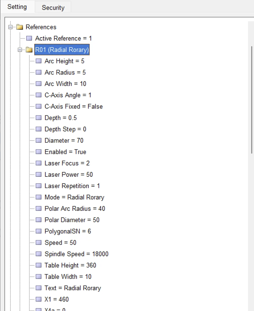
Reference – How it works and what you can do with it
Radonix lets you create up to 20 independent “References” (R01 – R20).
Think of each Reference as a complete job-profile that stores every coordinate, depth and speed setting needed for one class of workpiece (e.g., a 64 mm gold bangle, a 70 mm silver ring, a laser-only pass, …).
Each reference involves X1 , X2 , Y2 , Z1 , Z2 , Z3 , Z4 , ….. so the values on the surface that are entered will be save here
| Parameter | Sample Value | Technical Meaning / Application |
|---|---|---|
| Arc Height | 5 mm | Height of the arc after unwrapping; a positive value means the design rises 5 mm above the baseline. |
| Arc Radius | 5 mm | Radius of the arc; used to engrave a curved band on a domed (Bomb) surface. |
| Arc Width | 10 mm | Horizontal length (X direction) of the arc in flat view. |
| C-Axis Angle | 1° | Rotation offset around the ring; e.g., 1° to shift the design away from a weld line or fixture mark. |
| C-Axis Fixed | False | False means the C-axis rotates freely during the operation. |
| Depth / Depth Step | 0.5 mm / 0 | Engraving depth is 0.5 mm in a single pass (no layering). |
| Diameter | 70 mm | Outer diameter of the ring for this reference. |
| Enabled | True | Marks this reference as active and included in program execution. |
| Laser Focus / Power / Repetition | 2 / 50% / 1 | Z-focus at +2 mm, laser power 50%, one pass along the path. |
| Mode | Radial Rotary | The flat design is wrapped around the ring in a circular (C-axis) motion. |
| Polar Arc Radius / Polar Diameter | 40 mm / 50 mm | Reference radius/diameter for coordinate conversion in polar mode; usually matches the real ring size. |
| PolygonalSN | 6 | When exporting to legacy postprocessors, circles are approximated with 6 straight segments. |
| Speed | 50 mm/s | Feed rate, used if the G-code does not contain an F command. |
| Spindle Speed | 18,000 rpm | Default spindle rotation speed. |
| Table Height / Width | 360 mm / 10 mm | Dimensions of the unwrapped workspace; height = 360° (degrees), width = band width. |
| Text | “Radial Rotary” | Freeform label or comment for this reference. |
Parameters in System :
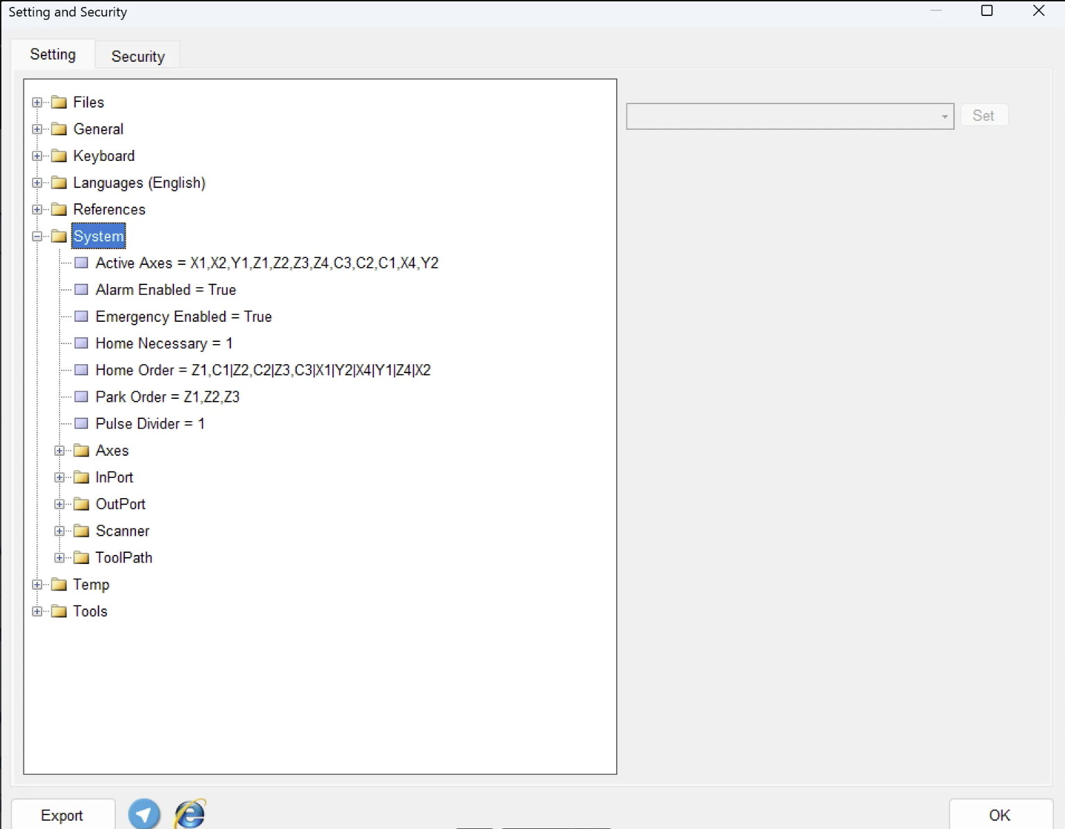
| Parameter | Sample Value | Technical Meaning | Practical Note |
|---|---|---|---|
| Active Axes | X1,X2,Y1,Z1,Z2,Z3,Z4,C3,C2,C1,X4,Y2 | List of all axes controlled by the system. The order here defines how they appear in the UI and logs. | If you add/remove an axis (e.g., installing a new Z4), update this list. After editing, Save Settings and restart the controller. |
| Alarm Enabled | True | Enables the software alarm generator (e.g., Over-travel, Following Error, Overheat, Air Pressure). | Keep this set to True. Only disable temporarily during short-term diagnostics. |
| Emergency Enabled | True | When set to True, the Emergency input (IN‑01) triggers a hardware-level power cut. | Never disable in standard operational mode. |
| Home Necessary | 1 | 1 means full homing is required before running any program; 0 allows execution without homing. | Recommended to keep 1 to avoid origin-related errors. |
| Park Order | Z1,Z2,Z3 | Axes that return to safe Park Position during Park or shutdown operations. | Usually Z axes are sufficient. Adding X/Y extends shutdown time but may help with sensitive fixtures. |
| Pulse Divider | 1 | Output pulse division ratio for stepper/servo drives. Modern systems typically use 1 (no division). | Only change if using older stepper drives needing ½ or ¼ pulse inputs. Incorrect values can cause step errors. |
Axis
Every Axis node in Radonix (X, Y, Z, C, etc.) carries the same set of core fields.
Together they control three things:
- Motion quality – how fast and how smoothly the slide starts-stops.
- Homing logic – where the machine finds zero and how far it backs off.
- Safety limits – software windows that prevent over-travel or reverse polarity.
Once you grasp what each field does, tuning one axis is exactly like tuning any other.
Field | What it controls | Typical tweak scenario |
|---|---|---|
Acceleration | This variable is used to determine the axis movement acceleration in terms of units/s2. The value of this variable does not affect the acceleration of the program execution by ToolPath. The appropriate value for this variable is determined by considering the stiffness, axis weight, and motor power. In general, it can be said that stiffness and axis weight have an inverse relationship, and motor power has a direct relationship with the value of this variable. | Lower if you hear thumps; raise to shorten cycle time once the servo keeps up. |
Alarm Enabled | Turns servo-fault monitoring on/off. | Keep True; set False only for brief bench tests. |
Direction | Software polarity (Positive ↔ Negative). | Flip if “X +” jogs the wrong way after rewiring. |
Displace Reference | Global offset added after homing. | Leave 0 unless you must shift every coordinate for that axis. |
Home Detect Velocity | This variable is used to determine the speed of the axis after the home sensor is detected. The value of this variable | 1–3 units/s; cut in half if the axis overshoots the sensor. |
Home Direction | This variable is used to determine the direction of axis movement towards the home sensor. Therefore, using this variable, the location of the home sensor can be defined | Change when the limit switch is moved to the opposite end. |
Home Displace | This variable is used to determine the direction of axis movement towards the home sensor. Therefore, using this variable, the location of the home sensor can be defined | Enter the dial-gauge (or degree-wheel) reading so absolute readout is 0.000 at the real datum. |
Home Location | This variable is used to determine the coordinates of the home point after the home sensor is activated. In other words, if the position of the home point is something other than MinCourse or MaxCourse, the numerical value of the home point can be determined by this variable. | Leave blank to stay on zero; enter 90 ° or +50 mm if you want automatic retract. |
Home Velocity | The homing speed can be determined by this variable. | Reduce if it bangs the stop; raise if it wastes time. |
Maximum Course | Positive soft-limit. | Shrink to protect wiring; stretch if you add longer travel. |
Maximum Velocity | Absolute speed ceiling. | Key in the real capability (e.g., 120 °/s); blank uses a generic default. |
Minimum Course | Negative soft-limit. | 0 for one-way rotaries; negative value for two-way axes. |
Step | Resolution (mm / pulse or ° / pulse). | Recalculate only after changing encoder, screw pitch or gearbox; wrong value = size errors in parts. |
Inports :
is the identifier for the pin number of the digital inputs of the controller. The variable “Enabled” is defined as True or False. If this variable is False, the input port in question is generally deactivated and ignored. If this variable is True, the input port in question is activated and can be used according to the designated link.
Digital Inputs (DIs) are 24 V sensor lines that tell the Radonix controller what the machine is doing. Each DI is linked—under Settings ► Inputs—to a name such as HomeX1, Emergency, or ClampSensor.When the connected switch or sensor goes HIGH, the controller instantly updates its logic (stop, home, interlock, etc.). All DIs are fail-safe: if the signal drops during a cycle, Radonix halts motion and raises an alarm. You can watch every DI live or force-invert its logic in the Diagnostics panel to confirm correct wiring.
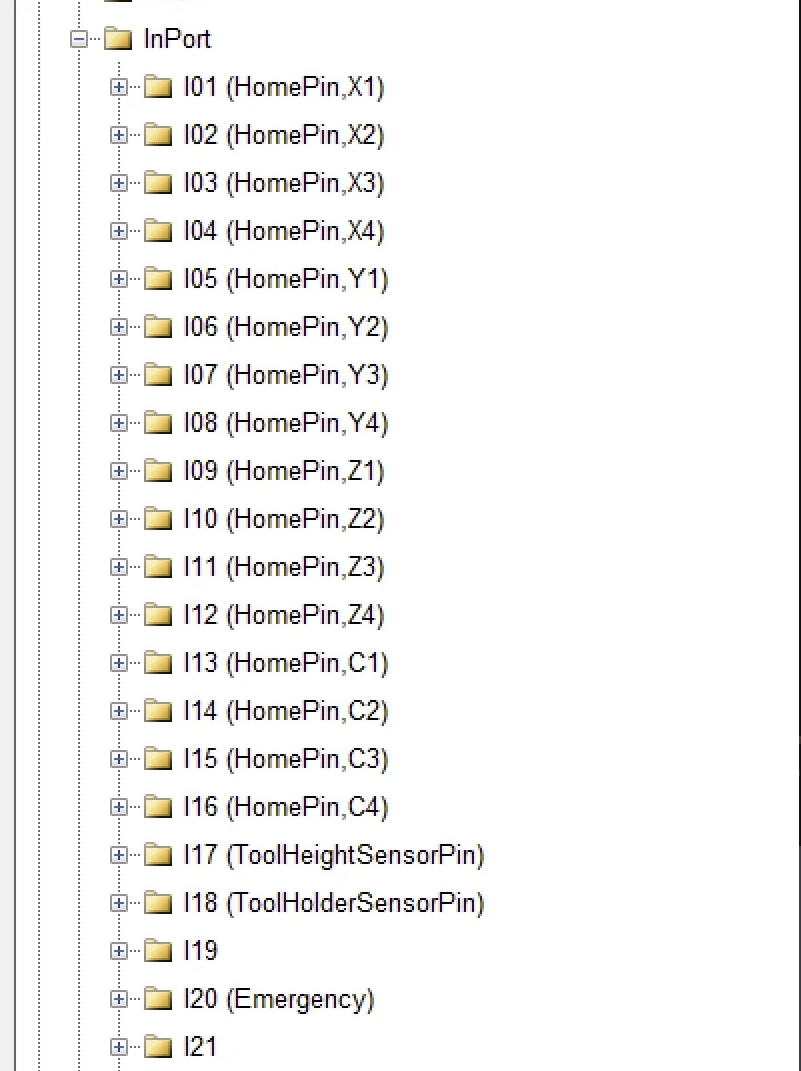
This photo shows a sample of the input settings, all of which are fully customizable. Earlier, we discussed the overall structure and the role of each axis link.
Outports :
Digital Outputs (DOs) are the Radonix controller’s 24 V on/off channels that drive external devices. Each DO is mapped—via Settings ► OutPort —to a tag like ClampPin or LaserEnabledPin . When G-code (e.g., M62) or a GUI button calls that tag, the controller pulls the line high, energising a solenoid, relay, light, etc. DOs drop to LOW automatically on E-STOP or power-loss, putting valves and drives in a safe state. You can manually toggle any DO in the Diagnostics window to verify wiring or reassign functions without changing firmware.
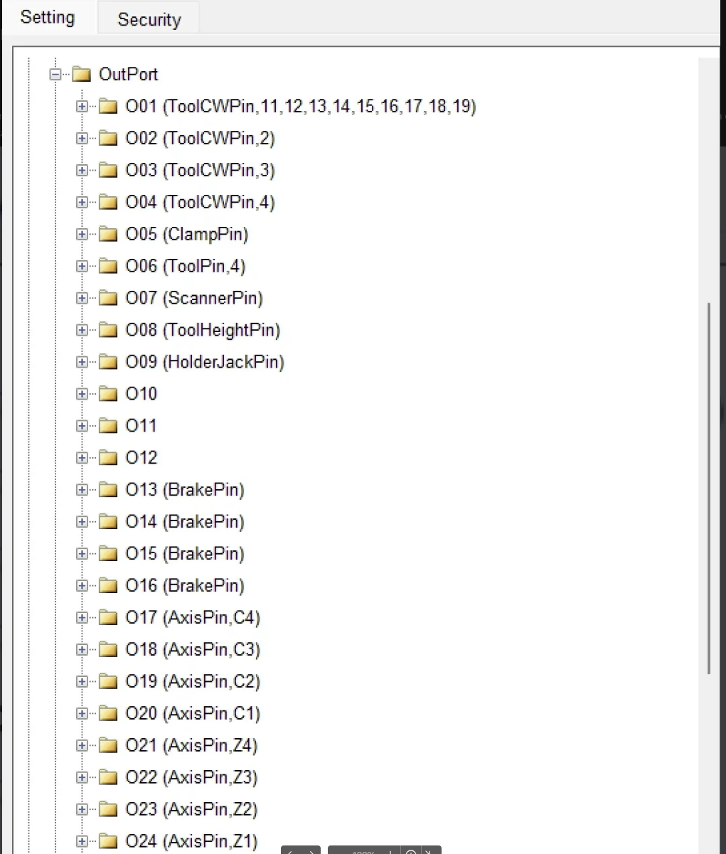
This photo shows a sample of the input settings, all of which are fully customizable. Earlier, we discussed the overall structure and the role of each axis link.
Scanner Settings
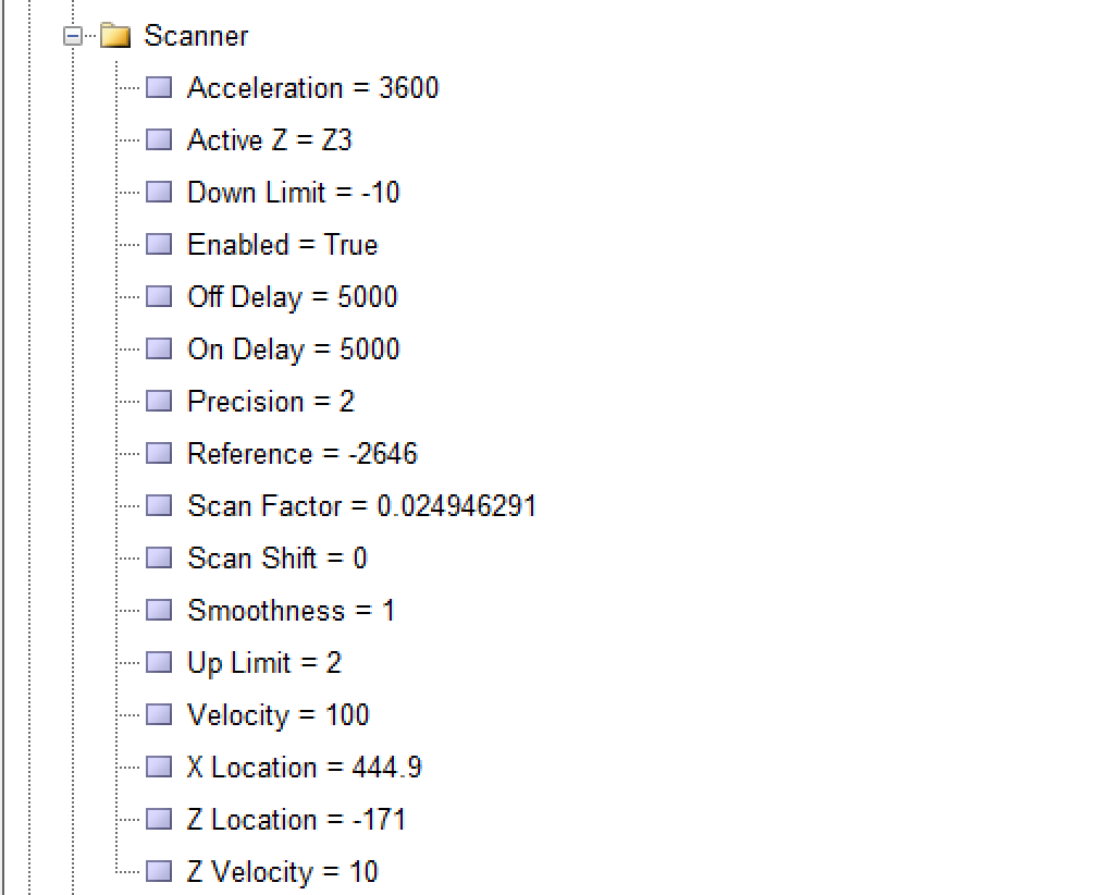
- Acceleration = 3600
- Purpose: Defines how quickly the scanner’s motion (often in the Z or other axes) accelerates, typically measured in mm/s².
- Usage Note: A higher value allows faster ramp-up to full speed but can introduce mechanical stress or vibration. A lower value provides smoother starts and stops.
- Active Z = Z3
- Purpose: Indicates which Z-axis (or which Z-offset) is currently “active” for scanning operations.
- Usage Note: Systems may have multiple Z references (e.g., Z1, Z2, Z3). Ensure the correct Z-axis or offset is selected based on your machine configuration.
- Down Limit = -10
- Purpose: Sets the lower boundary (limit) in the negative or downward Z direction that the scanner or probe is allowed to reach.
- Usage Note: If the scan head or probe goes beyond this value, the machine may trigger a limit switch or raise an error to prevent collisions.
- Enabled = True
- Purpose: Toggles the scanner’s functionality on or off.
- Usage Note: When set to False, the scanner features are disabled or ignored by the software.
- Off Delay = 5000
- Purpose: A time delay (likely in milliseconds) after the scanner finishes its operation or is turned off.
- Usage Note: Allows the system to stabilize or wait a short period before proceeding with another command, preventing abrupt transitions.
- On Delay = 5000
- Purpose: A time delay (in milliseconds) before the scanner begins its operation or is switched on.
- Usage Note: Useful when the scanner or laser requires time to warm up or to ensure the material is in position before scanning starts.
- Precision = 2
- Purpose: Defines the resolution or decimal precision the scanner uses for measurements.
- Usage Note: A value of 2 might represent 2 decimal places or a certain micrometer-level precision, depending on your system’s units.
- Reference = -2646
- Purpose: Establishes a reference offset for the scanner’s coordinate system, often used for homing or zeroing.
- Usage Note: If your scanning device or fixture has a known offset from the machine origin, this parameter ensures scans align correctly with the rest of your setup.
- Scan Factor = 0.024946291
- Purpose: A calibration coefficient indicating how the software translates sensor readings into real-world measurements (sometimes related to the reflectivity or geometry of the surface).
- Usage Note: If you change the hardware or scanning approach, you may need to re-calculate this factor for accurate results.
- Scan Shift = 0
- Purpose: A horizontal or vertical shift (depending on the setup) applied to all scan data, often used to align scans with a known origin.
- Usage Note: 0 means no shift is applied. Adjust if your scanned output is offset from your expected coordinates.
- Smoothness = 1
- Purpose: Adjusts how much smoothing or filtering is applied to the scan data.
Procedure for Laser Surface Scanning on Gold Bangles or Rings
- Home the Machine
- First, send the device or scanner to the Home Position to start from a precise and known reference point.
- Open Your Design
- Open the desired design or project file in the software.
- Before scanning, ensure all necessary parameters (such as dimensions and material type) are correctly set.
- Press the Scan Icon (Preparing for Calibration)
- Locate and click the Scan icon (usually next to the Help icon) to enter scan mode.
- Important: At this stage, the main goal is calibration. The Run or Play buttons—used to execute G-Code based on the surface scan—should only be used after a successful calibration.
- Attach Calibration Sticker (If Needed)
- Before beginning calibration, affix a small calibration sticker or substance onto the gold surface of the workpiece.
- Suggested Dimensions: Around 5 mm in height, and wide enough to match the width of the bangle or workpiece, so the laser can accurately detect slopes and reflections.
- This sticker has a slight inclination on both sides, helping the laser assess angles and reflections more precisely.
- Press the Calibrate Button
- Click Calibrate to have the scanner move back and forth at a 45-degree angle, determining optimal scanning parameters.
- Monitor the scanner’s movement to ensure there are no obstructions or excessive vibrations.
- Check the Scanfactor Value
- After calibration, the software displays a parameter called Scanfactor.
- Optimal Value: Below 1 indicates successful calibration and an “OK” status.
- Above 1: Implies the calibration was not optimal. Reposition the sticker or clean the workpiece surface and repeat the calibration.
- If Scanfactor remains above 1 despite these adjustments, electrical noise may be interfering. In this case, check your wiring and grounding to ensure proper connections.
- Run or Play After Calibration
- Once calibration succeeds (Scanfactor < 1), you can use Run or Play to execute the G-Code based on the newly calibrated surface data.
- Monitor the process to ensure the workpiece surface is fully captured without missing areas.
- Review and Save
- After scanning or running the G-Code, inspect the resulting data to ensure it is complete and clear.
- Save the scan data to the project file or export it in the desired format.
Important Tips and Recommendations
- Sticker Quality: Use a sticker or substance that provides a uniform surface for the laser beam.
- Surface Cleanliness: Clean the gold surface of any oils or contaminants so the laser reflects properly.
- Recalibration: If the Scanfactor remains above 1, check the sticker placement or mechanical settings and calibrate again.
- Noise and Connections: If the value still does not drop below 1, consider potential electrical noise; check all wiring and grounding.
- Safety: Always follow proper safety guidelines when working with reflective metals like gold and using laser beams.
By following these steps, you can achieve a precise and high-quality scan of your gold bangle or ring, and use the resulting data for design, engraving, or other related processes.
Toolpath
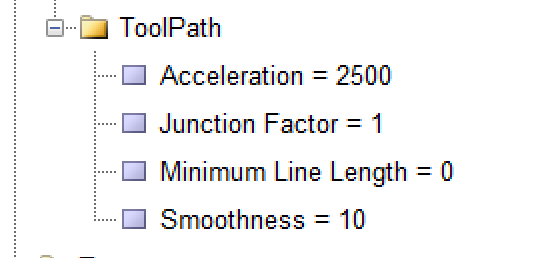
Acceleration
This variable is used to determine the acceleration of the axes simultaneously during program execution in units of unit/s. The appropriate value for this variable is determined taking into account the inertia, axis weight, and motor power. This value can be calculated mechanically and approximately. Generally, it can be said that there is an inverse relationship between inertia and axis weight and a direct relationship between motor power and the value of this variable.
Junction Factor
Software programs that convert motion paths into G-code usually simulate curved paths using line segments. There are angles between these lines, and based on these angles, the length of the lines, and the motion acceleration defined for the ToolPath, the maximum speed allowed for passing these intersections is calculated. This variable is actually a coefficient that is multiplied by the calculated maximum speed.
MinLineLength
When this parameter is zero, the averages of the steps are merged and a vector is obtained. In other words, if this parameter is zero, 10 times the merging of steps is considered as the smallest linear value that should be accepted, and by doing so, smaller lines than that value are ignored and connected to the next line. For example, if the steps are 1 millimeter and this parameter is zero, 10 times the steps are considered as the smallest value, meaning lines smaller than 0.1 millimeters are connected to the next line, while lines 0.1 millimeters or larger are executed without any change.
Smoothness
This variable is used to create a smoother and more uniform motion. In fact, the velocity curve changes from linear to an S-curve. As the value of this variable increases, the curvature of the S-curve also increases. If the speed or acceleration of the device is high, it is better not to set the value of this variable too high. The value that can be defined for this variable is a number between 1 and 250 milliseconds.